Vehicle information
| Brand: | Saab |
| Model: | 9-5 |
| Year: | 1999 |
| Engine: | 2.0 L |
| Engine code: | B205E |
| Cylinder count: | 4 |
| Fuel type: | Petrol |
| Motor management system: | Trionic T7 |
Used equipment

Automotive Test Scope ATS5004D
4 channel automotive oscilloscope with differential inputs
Measure lead TP-C1812B
low noise differential BNC to banana measuring lead, 3 m
Back Probe TP-BP85
thin and flexible back probe
The Automotive Test Scope ATS5004D is in this article also referred to as automotive oscilloscope, as diagnosis oscilloscope and as lab scope.
Problem description
A 1999 Saab 9-5 shows an intermittent problem. Occasionally, the engine will "hiccup" but then continue to work properly. The garage could not find any problems, because no fault codes were stored. Since the hiccups occurred only occasionally and they would not affect using the car, the owner could live with it. At some point, the problem became worse and in one occasion, the owner could only start the car after 20 minutes of trying. The problem was now occurring on a regular basis and finally the garage experienced it as well. They observed that no spark was generated by the special Saab Direct Injection (DI) module and concluded it was defective and needed replacement. Unfortunately, when the owner had his car with replaced module back the next day, it appeared that the problem was not solved. The car was then brought to GMTO for thorough examination.
Background information
Direct Ignition
Saab equips their cars with a special Direct Ignition system. The ignition system together with the ignition coils form a single cassette filled with transformer oil. It is placed directly on the spark plugs, without the need for a distributor nor spark plug cables. The DI system makes a camshaft sensor redundant, but a crankshaft sensor is still used.
When an engine has no camshaft sensor, the position of the camshaft is not known during start-up. It is however still possible to let the engine run, by driving the injectors and ignition two by two (DIS 1-4 and 2-3). To use sequential injection instead of DIS, adding a camshaft sensor would suffice. Saab however decided to follow a different path.
Combustion detection
Each spark plug has its own ignition coil which is combined with a special circuit. When they are not fired, the system puts a low voltage over the spark plugs to measure ionization in the cylinders. The ionic current measurement is used to determine whether the mixture in a specific cylinder ignites properly. This information can be used to detect a misfire. In the first stage of starting the engine, the Engine Control Module (ECM) does not know the proper ignition sequence yet and it will drive the injectors and ignition two by two. This will always lead to a proper ignition in one cylinder of each cylinder pair. That ignition is detected by the system, which then determines the proper injection and ignition sequence. Figure 1 clearly shows the change in injection and ignition pattern.
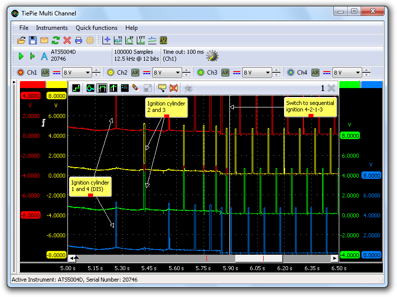
The four control signals for the individual ignition coils are measured with a automotive diagnostic oscilloscope. First the coils for cylinder 1 (top) and 4 (bottom) are driven and then cylinders 2 and 3 (center). After a few pulses (approximately 2 revolutions), the ECM has recognized the ignitions and determined the proper sequence and switches to a sequential pattern.
The DI cassette has two ignition detection terminals. The signal for the ignition detection of cylinders 1 and 2 can be found on pin 8. The signal for cylinders 3 and 4 on pin 9. Figure 2 shows the ignition control signal for cylinder 1 measured by channel 1 of the automotive lab scope. The ignition detection signal for cylinders 1 and 2 is measured by channel 2 and an injector signal is measured on channel 3.
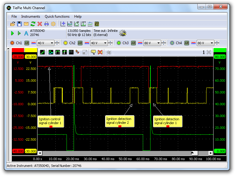
The scope image in Figure 2 shows a wide pulse in the ignition detection signal on Ch2 at the time of the ignition control pulse on Ch1. This wide pulse indicates that an ignition took place in this cylinder. Just before this wide pulse, another wide pulse is visible. This is the ignition detection for cylinder 2, which fires before cylinder 1.
Measuring
With problems as this car exhibits, it is good practice to start measuring the basic signals that are required for the ECM to let the engine run. These signals are the ignition control signal, injection control signal and crankshaft sensor signal. The automotive lab scope is set to measure for a long time at high speed, using a manual trigger button to trigger the measurement when the malfunction occurs. The lab scope is already measuring before the button is pressed, so the measurement shows the signals even before the time the button was pressed. When the engine fails while driving the car, a single press on the button will capture the signals and store them. The same signals were measured as in Figure 2, with the addition of the crankshaft signal on Ch4.
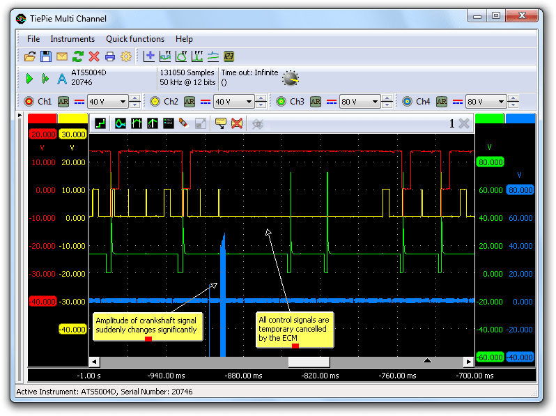
Figure 3 shows the signals that were captured when the car was driven and the engine failed. The bottom signal shows a strange anomaly: the crankshaft signal suddenly increases more than 20 times in amplitude and then falls back to the original, rather low amplitude. The top three signals show that both ignition control and injection control signals were missing and as an obvious result the ignition detection signal as well.
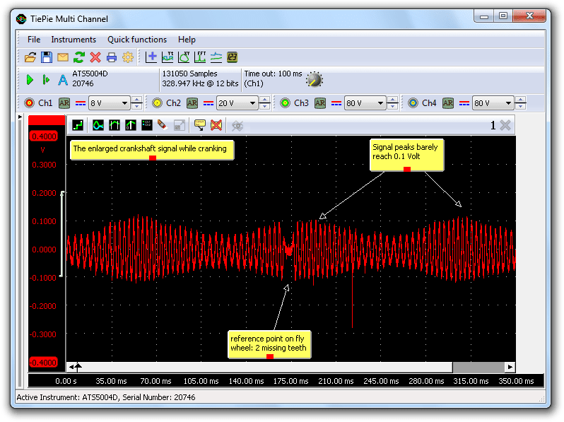
After the measurement, the engine was stopped and then it would no longer start. The only present signal was the crankshaft signal. Although very low, it showed the proper pattern. Figure 4 shows a detailed measurement of the crankshaft signal, indicating that the signal peaks barely reach 0.1 V, which is far too low to let the engine run properly.
Cause
After letting the engine cool down, it would start again and the crankshaft signal was a lot larger again. At some points during driving, it even reached peaks well over 80 V. It turned out that the internal resistance of the sensor was a lot higher in warm condition than in cold condition. Conclusion: crankshaft sensor defective.
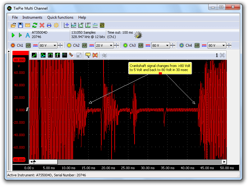
But why would the engine keep running with a defective sensor? The engine would most of the time start properly, because it was cold and the sensor would behave normal then. Once warm, during driving, the sensor could be shortly interrupted, causing a large change in sensor signal amplitude. The ECM would stop the control signals. However, the signal remained high enough for the ECM to recognize crankshaft position and rev count, so the ECM would start generating the control signals again, causing the engine to "hiccup". More measurements revealed several other problems in the crankshaft signal, as can be seen in Figure 5.
Solution
The problems were solved by replacing the crankshaft sensor.
Conclusion
The garage concluded to quickly that the DI-cassette had to be defective because it did not generate ignition signals. When a system is built from a chain of components and the last component in the chain does not send out signals, it does not mean that this last component is defective. It can very well be that one of the components earlier in the chain is defective, resulting in the last component not getting the required input to generate the correct output signals. It is therefore important to always measure earlier in the chain to check whether the required signals are present there. By doing this systematically, the culprit will always show up.
For systematically checking components, a good automotive diagnostic oscilloscope is indispensable. Problems in signals can be such that they are unable to find with simple test equipment. With e.g. a multimeter the short (< 30 ms) voltage jumps in the crankshaft signal could not have been found.
R. Metzelaar