Vehicle information
| Brand: | Volkswagen |
| Model: | Golf GTI |
| Year: | 1995 |
| Engine: | 2.0L |
| Engine code: | ABF |
| Cylinder count: | 4 |
| Fuel type: | Petrol |
| Motor management system: | Digifant 3.2 |
Used equipment

Automotive Test Scope ATS5000
2 channel automotive oscilloscope with Arbitrary Waveform Generator
The Automotive Test Scope ATS5000 oscilloscope is in this article also referred to as automotive oscilloscope, as Diagnosis Oscilloscope or as lab scope.
Problem description
The car in question runs fine for several kilometers but than suddenly starts running roughly. The garage already tried several things, from changing ECM, Hall sensor and because sometimes fault code Oxygen sensor malfunction was set, this sensor as well. The VW dealer who also looked at it, did not know what to do and delivered the car back to the garage, not repaired. The car was then delivered to GMTO for a thorough analysis.
Holding back of the engine
As usual we start our investigation by monitoring the most vital control signals of the engine management system, the injector and the ignition control with an automotive oscilloscope. The GMTO Automotive Test and Information System ATIS has a pre defined measurement setting for measuring these signals. Activating this setting loads the proper instrument setup into the lab scope with a click of a button, without tedious setting up of the instrument. The measurement setting uses the manual trigger button which is connected to the diagnostic oscilloscope using a long, flexible cable. Pressing this button will trigger the measurement, which will also capture the signals before the button was pressed. That way, if one single hitch would occur, it will be captured and we can analyze it on the automotive oscilloscope.
The measurement was activated an we and went driving. At first the car behaved like it should do. After about 6 km we did encounter the failure and the signals were frozen. This action resulted in a scope picture shown in Figure 1.
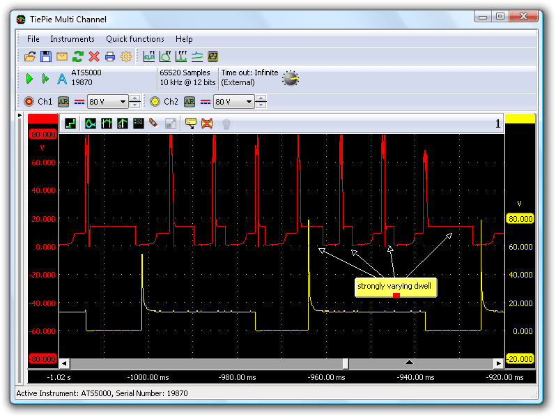
Evident is that the primary ignition coil control signal shows mistakes and besides missing a spark also displays a varying dwell control. The control signal of the injector shows no problem at all, a stable signal during a long period can be seen. But the engine obviously has to get its spark every compression stroke. If these misfires happen more often the oxygen sensor will detect too much oxygen in the exhaust gases and it is plausible that the ECM might conclude that the oxygen sensor malfunctions. This could explain the fault code on this sensor.
First conclusion
The engine revolution sensors must be good because the injector still worked correctly.
The engine is equipped with a single point injection system called Digifant 3.2 and possesses besides a crank angle sensor (Hall-type) also a camshaft revolution sensor (Hall type). It can occur that when the camshaft sensor malfunctions, only the ignition fails and the injectors keep functioning properly. To be certain this was not the case we measured the camshaft revolution sensor and found the signal stable during the occurrence of the problem.
Unstable dwell
Back to the unstable varying dwell seen in the ignition control signal. A modern ignition module monitors the current that flows through the ignition coil. This current always increases according a specific curve and when the current reaches the correct value, the transistor is taken partially out off conduction. This shows as the period after the coil (negative) has been pulled to the ground and the voltage is about half of the battery voltage. A (too) long period can be the result of a low coil resistance. A (too) short period can be the result of a voltage supply problem on the coil (contact resistance) causing a too long time before the current reaches the correct value.
The automotive oscilloscope screen shows two different things:
- The absence of a spark, while the power supply is a stable 12 V
- An extremely variable dwell
The 12 V shows that the power supply on the ignition coil is not the problem because this voltage is measured, through the coil and wires, near the ignition module. What remains is the control of the ignition module because the ECM dictates the moments of switching the coil current on and off (dwell and timing).
Problems in ignition module control
A logical next step is to measure the control signal of the ignition module of the ECM. With the second channel of the diagnostic oscilloscope the injector control is measured again, to get a clear picture on the regularity in the system (Figure 2).
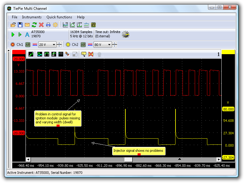
The automotive oscilloscope picture clearly shows a varying control during the problem. This signal is generated by the ECM and because we already checked the camshaft sensor we decided to check the crankshaft sensor. Both crankshaft and camshaft signal were measured during the occurrence of the problem and can be seen in the lab scope picture in Figure 3.
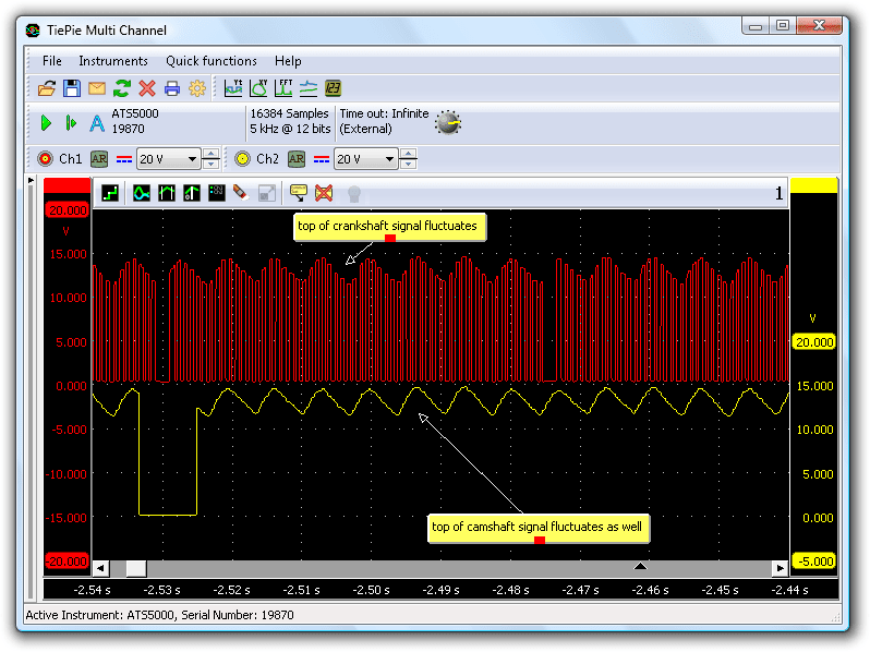
The measurement immediately caught our attention because something odd shows up. There was a correct regularity to be seen in the signal and also the missing lobe was visible but there was a strange fluctuation at the top of both signals. A a Hall-type sensor always switches a powered line to ground, when activated. When this sensor is not functioning properly, the 0 V level will be wrong. The high level of the output signal is generated by the ECM, if something is wrong there, it can be caused by the ECM or the power supply for the ECM.
Cause traced
Both power supply and ground of the Hall-type sensor come from the ECM and Figure 3 shows that the signal is properly switched to ground (measured against battery negative), so we can conclude that the ground of the ECM is well. We concentrated on the power supply of the ECM. From the wiring diagram of this system can be seen that the main power is provided through the system relay which is controlled by the ECM, which, in turn, is controlled by a wire coming from the ignition lock. There is even a special wire running from ECM to system relay, to keep the system relay activated even after the contact has been switched off. This allows to keep the cooling fan running even after the engine has been switched off. Measurements were made on the power supply of the ECM (pin 23 of ECM). When the problem occurred again it was obvious that the power supply was the cause of the problem. This can be seen in Figure 4.
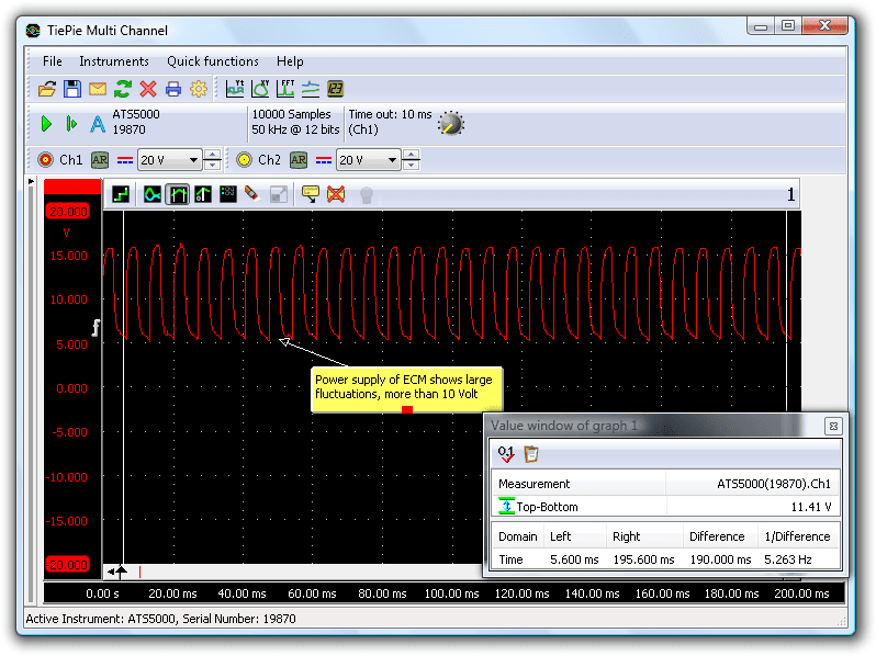
The power supply fluctuates heavily by so much as 10 V! That is not normal and the cause has almost certainly been traced.
Conclusion
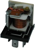
After this conclusion a few more measurements have been done on the control wire and power supply of the relay but no problems could be found there. The conclusion is that the relay itself must be the culprit (Figure 5). After replacing the relay the engine again behaved as it should.
Looking back this turned out to be an easy problem of a faulty component but was difficult enough for the mechanics involved in the garage. Because of the complexity of the system and amount of components it is not recommended to simply replace all components by trial and error. Measure at specific components may seem time consuming but in the end pays itself back if the correct pattern of fault finding is applied. Knowledge of the system, of course, is crucial.
R. Metzelaar