Actuator information
| Type: | Indirect injection |
|---|---|
| Power supply: | 12 V from system relay |
| Signal type: | Frequency and duty cycle varying |
| Signal level: | 0 V to 12 V and 80 V peak |
Workings of an injector
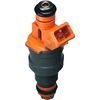
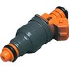
An injector sprays pressurized fuel into the inlet system or a cylinder. Due to the small opening in the injector and the high pressure, the fuel is atomized when it leaves the nozzle.
The particular injector measured for this article contains a metal pin that is kept pushed against a small opening by a spring. A coil is placed around the metal pin. A strong enough current flowing though the coil generates a magnetic field lifting the pin off the seat, opening the injector. While the current remains, the injector is held open. When the current is interrupted, the spring pressure pushes the metal pin back to its original position, closing the opening.
In most cases the injector has a power supply from a system relay and a switched ground wire connected to the ECU. In some cases the ECU controls the positive injector side and the negative side is permanently connected to ground.
A mono point injection system uses one injector placed just in front of the throttle valve. A multi point injection system uses one injector per cylinder placed in the inlet manifold just in front of the inlet port of a cylinder.
The injection moment is determined by the ECU according to the engine position which is determined from the crankshaft sensor signal and optionally the camshaft sensor signal. The ECU determines the injector's opening duration mainly from the engine temperature and demanded power.
Connecting the lab scope
Correct functioning of the injector can be checked by measuring the following signal voltages, see figure 1:
| Channel | Probe | Voltage | Range |
|---|---|---|---|
| 1 |  |
Signal voltage at injector | 80 V |
 |
Ground at battery | ||
| 2 |  |
Power supply at injector | 20 V |
|
Ground at battery |
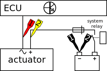
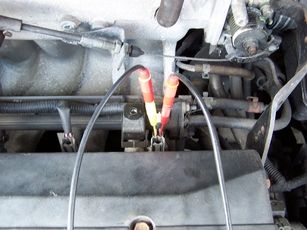
The lab scope is connected to the injector via a Measure lead TP-C1812B and Back Probe TP-BP85 and is set to normal scope mode.
Measuring
Figure 3 shows a waveform of an injector on an idling engine at operating temperature. This signal can be downloaded and used to correctly set up the lab scope or as reference signal.
Download Indirect injection voltage measurement
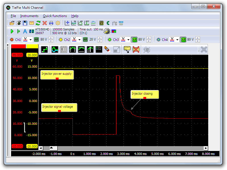
The signal on channel 1 (red) is measured at the negative side of the injector, which the ECU switches to ground. At the beginning of the measurement the injector is not activated, no current is flowing and the signal has the same value as the battery voltage. When injector is activated by the ECU at t=0, the signal voltage drops and a current starts flowing. The current builds up a magnetic field which, when strong enough to overcome the spring pressure, lifts the pin from the seat and opens the injector.
When the injector has been open long enough, the circuit is interrupted by the ECU at t = 2.6 ms. Because the circuit is interrupted, the current stops immediately. The sudden current change causes a high induction voltage. In this measurement the induction voltage is clipped by a diode to approximately 52 V. The built up magnetic field slowly decreases until it is too weak to overcome the spring force, which then pushes the pin back on its seat. The movement of the metal pin changes the magnetic field which affects the signal voltage. This is visible as a small hump in the signal.
The power supply of the injector measured with channel 2 (yellow) is equal to the battery voltage throughout the measurement. During the activation of the injector a current flows through it which can cause a little voltage drop. The voltage drop should not be too high because that would change the injector opening moment. See the injector current measurement for information about the injector current.
Diagnosis
Signal values may differ on different types of engine control units and injectors. Consult ATIS for information on specific engine control units and injectors.
The following signal deviations can indicate a problem:
-
No signal:
Cause: back probes have no connection (perform a connection test), no power supply, ECU amplifier defective, injector defective -
Signal voltage too high (with activated injector):
Cause: poor or no ground for ECU, resistance in wiring to ECU -
Noisy signal:
Cause: wires of power supply or signal damaged, poor connection in connector terminals, injector defective -
Signal shows an offset in relation to example signal:
Cause: poor or no ground for the ECU, resistance in wiring to ECU, scope is not set to DC coupling:
-
Power supply drops when injector is being opened:
Cause: poor connections in system relay or wiring to injector
RELATED PRODUCTS


RELATED ARTICLES
- Indirect injection current measurement
- With a lab scope an injector current is measured on an idling engine at operating temperature. The measured current is shown and can be downloaded. To help determining whether the injector is functioning correctly, different possible deviations from the example signal are mentioned along with possible causes.
- Toyota MR2 bad injector
- A Toyota MR2 is having problems after an engine replacement, fault code P0304 Cylinder #4 misfire detected occurs. The garage swaps several components but does not manage to fix the problem. Measurements with an automotive oscilloscope are required to find out that the fault code is somewhat misleading and the problem is not with cylinder #4
This document is subject to changes without notification. All rights reserved.
The information in this application note is carefully checked and is considered to be reliable, however TiePie engineering assumes no responsibility for any inaccuracies.
Safety warning:
- Before measuring, check that sources of dangerously high voltages are switched off or shielded from contact. Voltages considered to be dangerous are voltages over 30 V AC RMS, 42 V AC peak or 60 V DC.
- Keep a clean working environment when doing measurements.
- This measurement and procedures are a examples / measuring suggestions and are no prescribed protocols.
- TiePie engineering can not anticipate the safety actions that need to be taken to protect persons and appliances. Before starting a measurement, check which safety measures need to be applied.