Sensor information
| Type: | ABS sensor inductive |
|---|---|
| Power supply: | - |
| Signal type: | Amplitude and frequency varying |
| Signal level: | 0.4 V to 8 V |
Workings of the inductive ABS sensor
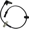
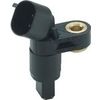
An anti lock braking system (ABS) sensor is used for determining wheel rotation speed to prevent wheel lock up when braking. The inductive ABS sensor consists of a permanent magnet with a coil around it. The magnetic field strength changes when a magnetism sensitive object passes through the magnetic field of the magnet. This changing of the magnetic field induces a voltage in the coil. The polarity of the induced voltage depends on the direction of the moving object, moving away or towards the sensor. This sensor doesn't need a power supply.
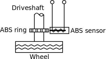
In most cases the object used to influence the magnetic field is a disk or ring with evenly distributed teeth, mounted on the driveshaft. When the driveshaft is rotating, the teeth are passing the sensor and the pattern in which they are placed is visible in the ABS sensor signal. Every period of the signal is a tooth passing the sensor. The frequency and amplitude of the signal depend on the rotation speed of the driveshaft and the amount of teeth on the disk or ring.
The inductive ABS sensor signal is monitored by a special ECU for the ABS system, the CAB (Controller Anti-lock Brake). The ECU uses the ABS sensor signal in two ways. When the wheel rotates fast enough for the ABS sensor signal to become larger than a certain threshold, the ECU determines the wheel speed using the rising and falling edges of the signal. When a wheel clearly has a lower speed than the other wheels or decelerates faster than the vehicle could, the ECU lowers the brake pressure for that particular wheel. This will result in a wheel speed increase and prevents skidding. When necessary, the brake pressure is continuously adjusted multiple times per second until the car nearly stops and the signal voltage falls below the threshold.
Connecting the lab scope
Correct functioning of the inductive ABS sensor can be checked by measuring the following signal voltages, see figure 2:
| Channel | Probe | Voltage | Range |
|---|---|---|---|
| 1 |  |
Signal at the positive side of the sensor | 2 V 1 |
 |
Signal at the negative side of the sensor |
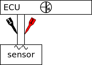
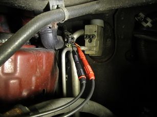
The lab scope is connected to the inductive ABS sensor via a Measure lead TP-C1812B and Back Probe TP-BP85. The lab scope is set to normal scope mode with the trigger-timeout at infinite. When a one-shot measurement is started with these settings, the measurement is performed when the wheel is turned (by hand).
 .
.
Measuring
Figure 4 shows a waveform of an inductive ABS sensor which is measured with the wheel turned by hand. This signal can be downloaded and used to correctly set up the lab scope or as reference signal.
Download inductive ABS sensor measurement
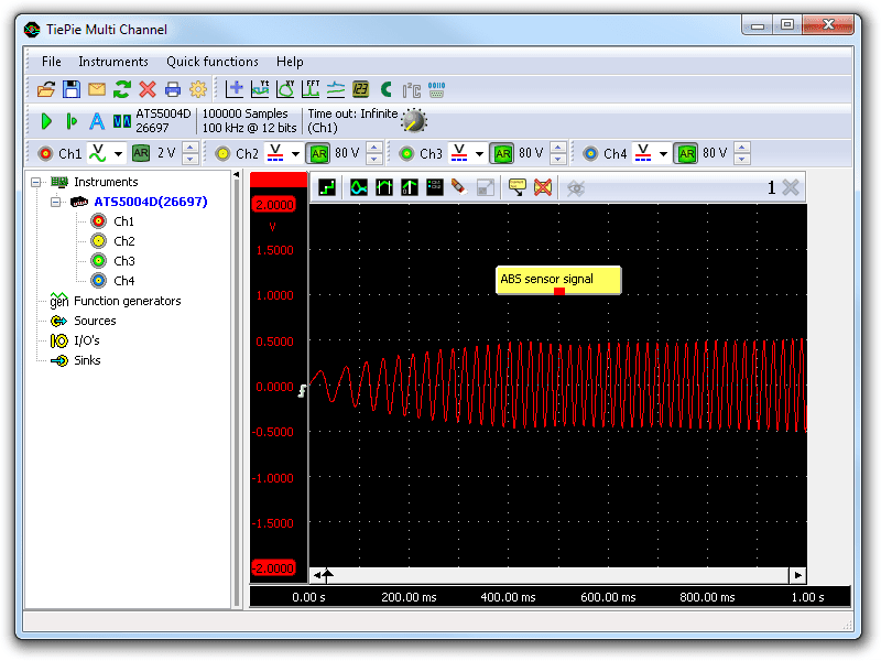
Channel 1 (red) shows the signal from the inductive ABS sensor. The signal starts with a low amplitude and frequency because the wheel rotates very slowly. Halfway during the measurement the wheel rotates at a speed that is sustained during the rest of the measurement.
The amplitude of the signal changes with the wheel rotation speed: with higher rotation speed the amplitude increases. The shown example waveform has an amplitude of 0.5 V at maximum. This is quite low because the wheel is turned by hand at low speed. The voltage will be higher when driving, but this is sufficient to test the ABS sensor. The exact amplitude of the signal is not important because the ECU uses the raising and falling edges to determine the wheel speed.
Diagnosis
Signal values may differ on different types of anti lock braking systems and ABS sensors. Consult ATIS for information on specific anti lock braking systems and ABS sensors.
The following signal deviations can indicate a problem:
-
No signal:
Cause: back probes have no connection (perform a connection test), sensor loose, sensor defective -
Noisy signal:
Cause: signal wires damaged, poor connection in connector terminals, sensor loose, sensor defective -
Signal shows an offset:
Cause: scope is not set to AC coupling:
-
Signal has faulty pattern:
Cause: tooth ring or disk damaged
RELATED PRODUCTS


RELATED ARTICLES
- Kia Carnival ABS problem
- The ABS warning light of a Kia Carnival would always light up when the speed exceeds 130 km per hour. The ABS wheel sensor was replaced twice, without solving the problem. Only by measuring with an automotive oscilloscope it became clear that a mechanical problem was causing the light to go on.
- ABS sensor Hall
- With a lab scope a 2 wire Hall effect ABS sensor signal voltage is measured with the wheel turned by hand. The signal from the sensor is shown and can be downloaded. To help determining whether the 2 wire Hall effect ABS sensor is functioning correctly, different deviations from the example signal are mentioned along with possible causes.
This document is subject to changes without notification. All rights reserved.
The information in this application note is carefully checked and is considered to be reliable, however TiePie engineering assumes no responsibility for any inaccuracies.
Safety warning:
- Before measuring, check that sources of dangerously high voltages are switched off or shielded from contact. Voltages considered to be dangerous are voltages over 30 V AC RMS, 42 V AC peak or 60 V DC.
- Keep a clean working environment when doing measurements.
- This measurement and procedures are a examples / measuring suggestions and are no prescribed protocols.
- TiePie engineering can not anticipate the safety actions that need to be taken to protect persons and appliances. Before starting a measurement, check which safety measures need to be applied.