Sensor information
| Type: | Two potentiometers |
|---|---|
| Power supply: | From ECU, 5 V and ground |
| Signal type: | Amplitude varying |
| Signal level: | 0.5 V to 4.0 V |
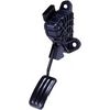
Workings of the accelerator pedal position sensor
The position of the acceleration pedal is measured with an acceleration pedal position sensor which is connected to the ECU. Most acceleration pedal position sensors are equipped with two potentiometers to increase reliability. Each potentiometer has its own power supply from the ECU, which means the number of connections can be up to 6. The potentiometer contains a carbon track connected to the power supply at one end and ground at the other. A slider mechanically connected to the accelerator pedal slides over the carbon track picking up the sensor voltage.
If the sensor contains two potentiometers, the power supply is usually connected in reverse to the second potentiometer. When the acceleration pedal is moved, the signal voltage of one potentiometer increases while the other decreases. The acceleration pedal position sensor in this measurement example also contains two potentiometers, but they are both connected the same way. As a result, both signals are equal except for a different offset.
Connecting the lab scope
Correct functioning of the accelerator pedal position sensor can be checked by measuring the following signal voltages, see figure 1:
| Channel | Probe | Voltage | Range |
|---|---|---|---|
| 1 |  |
Sensor output signal 1 | 8 V |
 |
Ground at battery | ||
| 2 |  |
Sensor output signal 2 | 8 V |
 |
Ground at battery | ||
| 3 |  |
Positive side of 1st potentiometer power supply | 8 V |
|
Negative side of 1st potentiometer power supply | ||
| 4 |  |
Positive side of 2nd potentiometer power supply | 8 V |
|
Negative side of 2nd potentiometer power supply |
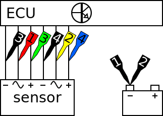
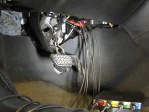
The lab scope is connected to the accelerator pedal position sensor via a Measure lead TP-C1812B and Back Probe TP-BP85 and set to recorder mode. In recorder mode a streaming measurement is performed, continuously displaying the signals live on screen. Because the measured signals vary slowly, the Automotive Test Scope ATS5004D is set to a slow measuring speed.
Measuring
Figure 3 shows waveforms of an accelerator pedal position sensor with the key turned on and engine off. This signal can be downloaded and used to correctly set up the lab scope or as reference signal.
Download acceleration pedal position sensor measurement
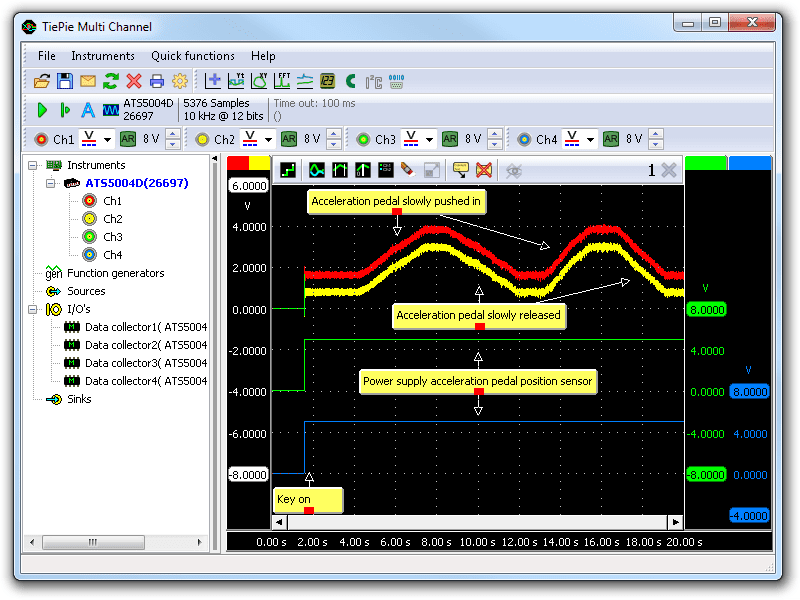
The signals from channel 1 (red) and channel 2 (yellow) are the two potentiometers of the acceleration pedal position sensor. The signal on channel 2 is offset by 0.75 V to the signal from channel 1 over the complete range of the sensor. At the beginning of the measurement the key is turned on, resulting in the powering up of the ECU which is the power supply of the acceleration pedal position sensor. Subsequently the acceleration pedal is slowly pushed in and released twice during this measurement, the second time a little faster than the fist time. Channel 3 (green) shows the power supply of the first potentiometer and channel 4 (blue) the power supply for the second potentiometer. Both power supplies should carry the same voltage.
Diagnosis
Signal values may differ on different types of engine control units and accelerator pedal position sensors. Consult ATIS for information on specific engine control units and accelerator pedal position sensors.
The following signal deviations can indicate a problem:
-
No signal:
Cause: back probes have no connection (perform a connection test), no power supply, sensor defective -
Signal voltage too high:
Cause: poor or no ground on power supply, resistance in wiring to ECU, sensor defective -
Noisy signal:
Cause: wiring of signal or power supply damaged, poor connection in connector terminals, sensor defective -
Signal shows an offset:
Cause: scope is not set to DC coupling: ,
poor or no ground on power supply, resistance in wiring to ECU, sensor defective
,
poor or no ground on power supply, resistance in wiring to ECU, sensor defective
RELATED PRODUCTS


RELATED ARTICLES
- Throttle valve Position Sensor Dual
- With a lab scope a throttle valve position sensor is measured with the key turned on and engine off. The signal from the sensor is shown and can be downloaded. To help determining whether a throttle valve position sensor is functioning correctly, different possible deviations from the example signal are mentioned along with possible causes.
- Throttle valve Position Sensor Single
- With a lab scope a throttle valve position sensor is measured with the key turned on and no running engine. The signal from the sensor is shown and can be downloaded. To help determining whether a throttle valve position sensor is functioning correctly, different possible deviations from the example signal are mentioned along with probable causes.
- Peugeot 205 holding back
- When a Peugeot 205 is performing a strong accelleration, it starts holding back. When it is cruising, nothing is wrong. Several components were replaced, without result. The automotive oscilloscope was used to measure various signals, which led to finding a simple mechanical problem.
This document is subject to changes without notification. All rights reserved.
The information in this application note is carefully checked and is considered to be reliable, however TiePie engineering assumes no responsibility for any inaccuracies.
Safety warning:
- Before measuring, check that sources of dangerously high voltages are switched off or shielded from contact. Voltages considered to be dangerous are voltages over 30 V AC RMS, 42 V AC peak or 60 V DC.
- Keep a clean working environment when doing measurements.
- This measurement and procedures are a examples / measuring suggestions and are no prescribed protocols.
- TiePie engineering can not anticipate the safety actions that need to be taken to protect persons and appliances. Before starting a measurement, check which safety measures need to be applied.