Sensor information
| Type: | Crankshaft sensor inductive |
|---|---|
| Power supply: | - |
| Signal type: | Frequency varying |
| Signal level: | ±0.25 V minimum up to ±60 V |
Workings of the inductive crankshaft sensor
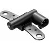
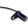
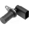
The inductive crankshaft sensor is constructed of a permanent magnet with a coil around it. The magnetic field strength changes when a magnetism sensitive object passes through the magnetic field of the magnet. This changing of the magnetic field induces a voltage in the coil. The polarity of the induced voltage depends on the direction of the moving object, moving away or towards the sensor. This sensor doesn't need a power supply.
In most cases the object used to influence the magnetic field is a disk or ring with evenly distributed teeth, mounted on the crankshaft or flywheel. When the crankshaft is rotating, the teeth are passing the sensor and the pattern in which they are placed is visible in the crankshaft sensor signal. Every period of the signal is a tooth passing the sensor. The frequency and amplitude of the signal depends on the rotation speed of the crankshaft and the amount of teeth on the disk or flywheel. The disk or ring usually has one or two teeth missing or a tooth that is bigger than the rest as a reference point so the ECU can determine the position of the crankshaft. The ECU uses the crankshaft position to determine when to inject the fuel and when to ignite it.
With a RPM I/O the crankshaft sensor signal can be converted to a signal that shows the course of the engine speed.
Connecting the lab scope
Correct functioning of the crankshaft sensor can be checked by measuring the following signal voltages, see figure 1:
| Channel | Probe | Voltage | Range |
|---|---|---|---|
| 1 |  |
Signal at the positive side of the sensor | 8 V 1 |
 |
Signal at the negative side of the sensor |
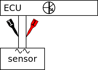
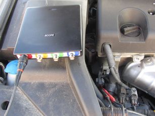
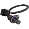
The lab scope is connected to the crankshaft sensor via a Measure lead TP-C1812B and Back Probe TP-BP85. The lab scope is set to normal scope mode with the trigger-timeout at infinite. When a one-shot measurement is started with these settings, the measurement is performed when the engine is cranked.
 .
.
Measuring
Figure 3 shows a waveform of a crankshaft sensor of an engine during cranking. This signal can be downloaded and used to correctly set up the lab scope or as reference signal.
Download crankshaft sensor inductive measured during cranking
Download crankshaft sensor inductive measured idling egnine
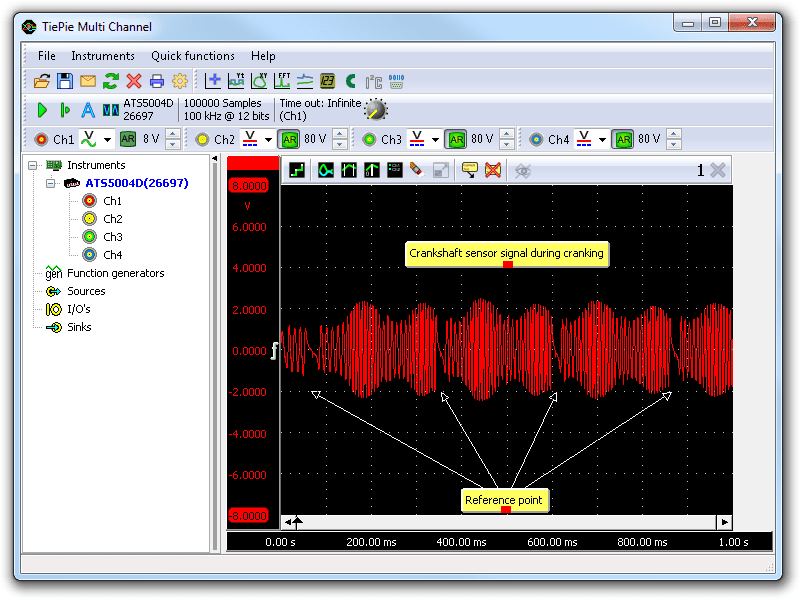
The crankshaft sensor signal voltage on channel 1 (red) shows amplitude changes during cranking. The changes are caused by the changes in engine speed during each compression stroke of a cylinder. The change in engine speed can also be seen reflected in the frequency variation of the signal. Clearly visible are the reference points caused by two missing teeth.
The signal amplitude must be 0.6 V at minimum for the ECU to recognize it. In the beginning of this measurement the amplitude is 0.7 V which is just enough. The signal amplitude varies with the engine speed: it is higher at higher rpms. The exact amplitude is not important because the ECU uses the flanks to determine the crankshaft position.
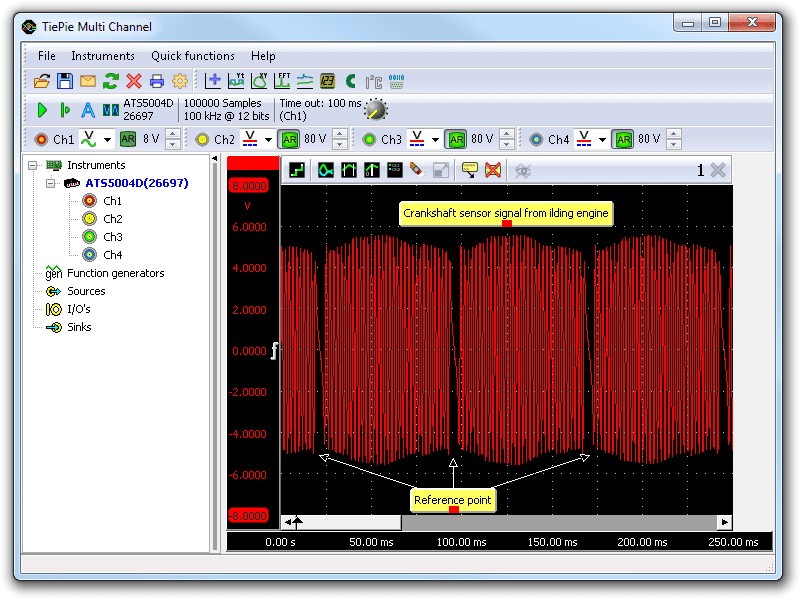
Figure 4 shows the signal of a crankshaft sensor of an idling engine. To make the amplitude difference clear, the measurement has been performed with the same settings as used for the previous measurement. The graph is zoomed in on the first quarter of the measurement to be able to see the signal periods. Also during idling the amplitude variations caused by the compression strokes are visible.
Diagnosis
Signal values may differ on different types of engine control units and crankshaft sensors. Consult ATIS for information on specific engine control units and crankshaft sensors.
The following signal deviations can indicate a problem:
-
No signal:
Cause: back probes have no connection (perform a connection test), sensor loose, sensor defective -
Signal shows more noise than example signal:
Cause: signal wires damaged, poor connection in connector terminals, sensor loose, sensor defective -
Signal shows an offset:
Cause: scope is not set to AC coupling:
-
Signal has faulty pattern:
Cause: cam or disk damaged
RELATED PRODUCTS


RELATED ARTICLES
- Crankshaft Hall
- With a lab scope a Hall effect crankshaft sensor is measured during cranking of an engine. The signal from the sensor is shown and can be downloaded. To help determining whether a Hall effect crankshaft sensor is functioning correctly, different possible deviations from the example signal are mentioned along with probable causes.
- Camshaft sensor inductive
- With a lab scope an inductive camshaft sensor is measured during cranking of an engine, as well as during idling. The signal from the sensor is shown and can be downloaded. To help determining whether an inductive camshaft sensor is functioning correctly, different possible deviations from the example signal are mentioned along with probable causes.
- Xantia refuses to run
- A 1999 Citroën Xantia had a new starter motor fitted, after which it would not run anymore. While cranking it would fire briefly and then die. The car’s battery had been disconnected for the starter motor job. A crankshaft sensor code was logged and thus the crankshaft sensor was replaced, regardless of the good signal. Later the ECM was replaced all with no positive results. The question was if the immobilizer could have reset itself by disconnecting the battery. Proper measuring revealed what the real problem was.
- Troublesome Volvo XC70
- A Volvo XC70 had serious engine related drivability problems. The engine lacked power, would hold back and even stall. Error codes indicated problems in two different areas. Replacing components did not improve things. Proper measuring with an automotive diagnostic oscilloscope revealed two independent problems. Fixing these solved all problems.
- Saab 9-5 with intermittent hiccups
- The engine of a 1999 Saab 9-5 intermittently shows a "hiccup" but then continues to run properly. Over time, the problem became worse and and at some point, the car would not start for 20 minutes. The owner consulted a garage that concluded that the special Direct Ignition cassette needed replacement. Unfortunately that did not solve the problem. Time to start measuring properly, using an automotive diagnostic oscilloscope.
This document is subject to changes without notification. All rights reserved.
The information in this application note is carefully checked and is considered to be reliable, however TiePie engineering assumes no responsibility for any inaccuracies.
Safety warning:
- Before measuring, check that sources of dangerously high voltages are switched off or shielded from contact. Voltages considered to be dangerous are voltages over 30 V AC RMS, 42 V AC peak or 60 V DC.
- Keep a clean working environment when doing measurements.
- This measurement and procedures are a examples / measuring suggestions and are no prescribed protocols.
- TiePie engineering can not anticipate the safety actions that need to be taken to protect persons and appliances. Before starting a measurement, check which safety measures need to be applied.