Actuator information
| Type: | Stepper motor |
|---|---|
| Power supply: | 12 V from system relay |
| Signal type: | Varying frequency and duty cycle |
| Signal level: | 0 V to 12 V and 40 V peak |
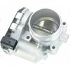
Workings of a throttle valve position stepper motor
In most engine management systems a throttle valve position control mechanism is used to control the amount of air entering the engine. This is commonly done with a DC motor but some applications use a stepper motor that works mechanically similar to a DC motor throttle valve position controller.
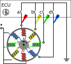
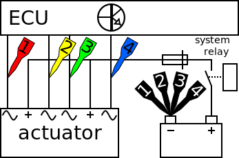
Like a DC motor, a stepper motor contains coils that can be powered to turn the axle of the motor. In the stepper motor in this measurement example, two opposite coils are connected in series, which is called a pole pair, see figure 1. Each pole pair is connected to its own terminal so that every pole pair can be individually powered. This makes it possible to move the axle a small amount of degrees, or step, per pole change. When a rotation is needed, the pole pairs can be switched sequentially to make the axle rotate. Since step size in degrees is known, the movement steps of the axle can be counted by the ECU to put it in a certain position without the need for a feedback position sensor.
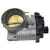
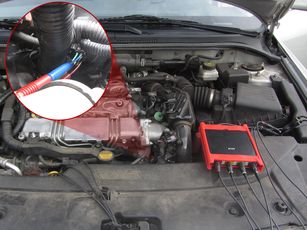
In this measurement, the throttle valve position stepper motor on a diesel engine is used. The throttle valve is situated between the inter cooler and inlet manifold and is used to control the amount of air entering the engine, to control the air pressure. This creates a lower pressure in the intake manifold so the EGR can be more effective and particle filter regeneration can be done. When stopping the engine, closing the throttle valve helps to bring the engine to a smoother stop.
Connecting the lab scope
Correct functioning of the throttle valve position stepper motor can be checked by measuring the following signal voltages, see figure 2:
| Channel | Probe | Voltage | Range |
|---|---|---|---|
| 1 |  |
Signal voltage stepper motor pole pair 1 | 40 V |
 |
Ground at battery | ||
| 2 |  |
Signal voltage stepper motor pole pair 2 | 40 V |
|
Ground at battery | ||
| 3 |  |
Signal voltage stepper motor pole pair 3 | 40 V |
|
Ground at battery | ||
| 4 |  |
Signal voltage stepper motor pole pair 4 | 40 V |
|
Ground at battery |
The lab scope is set to normal scope mode with the trigger-timeout at infinite. When a one-shot measurement is started with these settings, the measurement is performed when the throttle valve position stepper motor is activated.
Measuring
Figure 4 shows a waveform of a throttle valve position stepper motor of a car with revved engine at operating temperature. This signal can be downloaded and used to correctly set up the lab scope or as reference signal.
Download throttle valve position stepper motor measurement
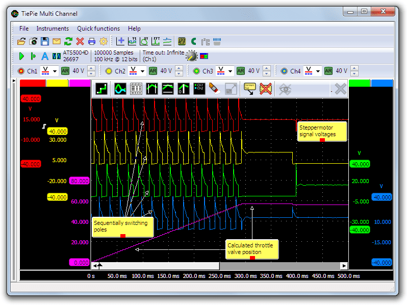
Channel 1 (red) shows the first pole pair, channel 2 (yellow) the second, channel 3 (green) the third and channel 4 (blue) the fourth. The purple line shows a calculated relative position of the throttle valve, determined by a Pulse decoder I/O using two pole pair signals. The signals in this measurement are sequential, meaning that the ECU is trying to move the throttle valve to a certain position. After the rapid sequential signals the ECU holds the stepper motor in the reached position, which can be seen as channel 3 is still activated. Then the activated pole pair changes back to channel 2 as the ECU makes one step back.
Diagnosis
Signal values may differ on different types of engine control units and throttle valve position stepper motors. Consult ATIS for information on specific engine control units and throttle valve position stepper motors.
The following signal deviations can indicate a problem:
-
No signal:
Cause: back probes have no connection (perform a connection test), no power supply, throttle valve position stepper motor defective -
Signal voltage too low:
Cause: poor power supply to throttle valve position stepper motor -
Noisy signal:
Cause: wiring of signal wire or power supply damaged, throttle valve position stepper motor defective -
Signal shows an offset in relation to the example signal:
Cause: scope is not set to DC coupling:
RELATED PRODUCTS


RELATED ARTICLES
- Throttle valve control motor DC measurement
- With a lab scope a throttle valve control motor signal voltage is measured with the key on and engine off. The signal from the actuator is shown and can be downloaded. To help determining whether the throttle valve control motor is functioning correctly, different deviations from the example signal are mentioned along with possible causes.
- Acceleration Pedal Sensor
- With a lab scope an acceleration pedal position sensor is measured with the key turned on and no running engine. The signal from the sensor is shown and can be downloaded. To help determining whether an acceleration pedal position sensor is functioning correctly, different possible deviations from the example signal are mentioned along with probable causes.
This document is subject to changes without notification. All rights reserved.
The information in this application note is carefully checked and is considered to be reliable, however TiePie engineering assumes no responsibility for any inaccuracies.
Safety warning:
- Before measuring, check that sources of dangerously high voltages are switched off or shielded from contact. Voltages considered to be dangerous are voltages over 30 V AC RMS, 42 V AC peak or 60 V DC.
- Keep a clean working environment when doing measurements.
- This measurement and procedures are a examples / measuring suggestions and are no prescribed protocols.
- TiePie engineering can not anticipate the safety actions that need to be taken to protect persons and appliances. Before starting a measurement, check which safety measures need to be applied.