
Workings of a smooth running test
Many factors are contributing for an engine to be running smoothly and producing the desired amount of power. Mechanical components, electronical components and a correct functioning ECU are the main factors. When an engine is not running properly, a smooth running test can be performed to check if the main functions are working correctly. A smooth running test is done on engines that run troublesome, misfire or have erratic faults at certain RPMs.
A smooth running test is a measurement on the main inputs and outputs to diagnose if they are working properly. The main inputs are the crankshaft and camshaft sensors and main outputs are the injection en ignition signals. The crankshaft and camshaft sensors are position sensors used by the ECU to determine the position and the speed of the engine to adjust the output signals accordingly. The smooth running test can be used to check the camshaft and crankshaft timing, which can change due to a stretched or slipped timing belt or chain. Besides the crankshaft and camshaft sensor, the ECU uses signals of the coolant temperature sensor, mass air flow sensor and more sensors to determine the injection and ignition timing.
This measurement is performed on a good running engine, on an inductive crankshaft sensor, an inductive camshaft sensor, an indirect injector and the trigger signal of the COP ignition. Details of every component can be read in the individual articles, this measurement is performed to show the relation between these individual signals in a motor management system.
Connecting the lab scope
Performing a smooth running test can be done by measuring the crankshaft sensor, the camshaft sensor, the injection actuator and the ignition actuator signal voltages, see figure 1:
| Channel | Probe | Voltage | Range |
|---|---|---|---|
| 1 |  |
Signal at the positive side of the crankshaft sensor | 8 V |
 |
Signal at the negative side of the crankshaft sensor | ||
| 2 |  |
Signal at the positive side of the camshaft sensor | 4 V |
|
Signal at the negative side of the camshaft sensor | ||
| 3 |  |
Signal voltage at injector | 80 V |
|
Ground at battery | ||
| 4 |  |
Ignition trigger signal | 8 V |
 |
Ground at battery |
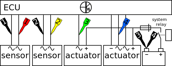
The lab scope is connected to the crankshaft sensor, camshaft sensor, injection signal and ignition signal via a Measure lead TP-C1812B and Back Probe TP-BP85 and set to is set to normal scope mode.
Measuring
Figure 3 shows waveforms of the crankshaft sensor, the camshaft sensor, the injector and the ignition of an engine running at idle speed. This signal can be downloaded and used to correctly set up the lab scope or as reference signal.
Download smooth running test measurement at idle speed
Download smooth running test measurement at 1800 RPM
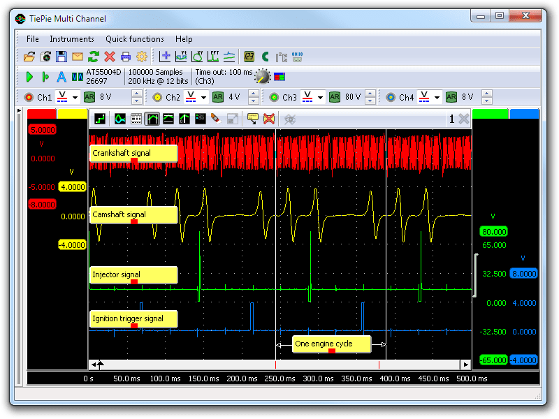
The following measured signals are shown:
- channel 1 (red) shows the crankshaft sensor signal
- channel 2 (yellow) shows the camshaft sensor signal
- channel 3 (green) shows the injection signal
- channel 4 (blue) shows the ignition trigger signal
One engine cycle, indicated in the bottom of the graph, contains two rotations of the crankshaft (visible by two sequential waveform patterns in the crankshaft signal) and one camshaft rotation (visible by a single waveform pattern). The ignition trigger signal has a rising edge which activates the COP ignition and the falling edge is the actual time when the ignition has to take place. During one engine cycle the injection take place at TDC (top dead center) when the intake stroke is starting. After this the compression stroke takes place and just before the next TDC an ignition takes place.
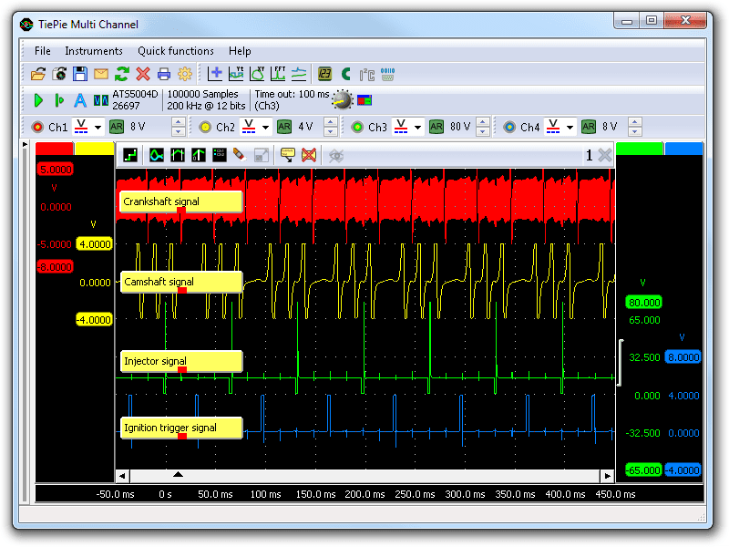
Figure 4 shows the same measurement with raised engine speed to 1800 RPM. The smooth running test is setup to measure the same signals at higher engine speeds. With the raised engine speed faults can show up, for example malfunctioning crankshaft sensor or camshaft sensor signals or missing injections or ignitions causing misfires.
When erratic or intermittent faults occur the intermittent fault measurement can be performed with the labscope still connected as in this measurement, using the settings described in the intermittent fault measurement applied.
Diagnosis
When an engine shows signs of running improperly and the signals appear to be correct other signals, for example the mass air flow sensor or coolant temperature sensor can be measured to check their condition.
For the signals measured in this measurement example can be referenced to the following measurements:
- the inductive crankshaft sensor,
- the inductive camshaft sensor,
- the indirect injection actuator,
- and the COP ignition.
RELATED PRODUCTS


RELATED ARTICLES
- inductive crankshaft sensor
- With a lab scope an inductive crankshaft sensor is measured during cranking of an engine, as well as during idling. The signal from the sensor is shown and can be downloaded. To help determining whether an inductive crankshaft sensor is functioning correctly, different possible deviations from the example signal are mentioned along with probable causes.
- Camshaft sensor inductive
- With a lab scope an inductive camshaft sensor is measured during cranking of an engine, as well as during idling. The signal from the sensor is shown and can be downloaded. To help determining whether an inductive camshaft sensor is functioning correctly, different possible deviations from the example signal are mentioned along with probable causes.
- Indirect injection voltage measurement
- A lab scope is used to measure an injector signal voltage on an idling engine at operating temperature. The signal from the sensor is shown and can be downloaded. To help determining whether the injector is functioning correctly, different possible deviations from the example signal are mentioned along with possible causes.
- COP ignition measurement
- With a lab scope a COP ignition is measured with a Coil-on-Plug probe TP-COP750. The signal from the COP ignition is shown and can be downloaded. To help determining whether the COP ignition is functioning correctly, different deviations from the example signal are mentioned along with possible causes.
This document is subject to changes without notification. All rights reserved.
The information in this application note is carefully checked and is considered to be reliable, however TiePie engineering assumes no responsibility for any inaccuracies.
Safety warning:
- Before measuring, check that sources of dangerously high voltages are switched off or shielded from contact. Voltages considered to be dangerous are voltages over 30 V AC RMS, 42 V AC peak or 60 V DC.
- Keep a clean working environment when doing measurements.
- This measurement and procedures are a examples / measuring suggestions and are no prescribed protocols.
- TiePie engineering can not anticipate the safety actions that need to be taken to protect persons and appliances. Before starting a measurement, check which safety measures need to be applied.