Sensor information
| Type: | Crankshaft sensor Hall-type |
|---|---|
| Power supply: | From system relay or ECU, 12 V or 5 V and ground |
| Signal type: | Frequency varying |
| Signal level: | Switching between 0 V and 5 V |
Workings of the crankshaft sensor
A Hall-sensor can be used to measure magnetic field strength. In the use for automotive applications the sensor placed next to or opposite of a permanent magnet. When a metal object passes the sensor, the magnetic field is disrupted. The sensor electronics convert the disruption of the magnetic field to a digital signal by pulling a voltage from the ECU to ground depending on the magnetic field strength.
The object that disrupts the magnetic field is often a metal disk or ring with a certain hole pattern placed on the end of the crankshaft. When the crankshaft rotates, the hole pattern is visible in the crankshaft sensor signal. The frequency of the signal depends of the amount of holes in the disk and how fast the crankshaft is rotating. The position of the engine can be determined from the combination of a camshaft and crankshaft signal.
Connecting the lab scope
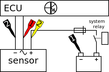
Correct functioning of the crankshaft sensor can be checked by measuring the following signal voltages, see figure 1:
| Channel | Probe | Voltage | Range |
|---|---|---|---|
| 1 |  |
Sensor output signal | 8 V |
 |
Ground at battery | ||
| 2 |  |
Positive side of sensor power supply | 20 V |
|
Negative side of sensor power supply |
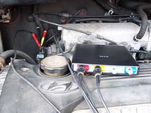
The lab scope is connected to the crankshaft sensor via a Measure lead TP-C1812B and Back Probe TP-BP85. The lab scope is set to normal scope mode with the trigger-timeout at infinite. When a one-shot measurement is started with these settings, the measurement is performed when the engine is cranked.
Measuring
Figure 3 shows a waveform of a crankshaft sensor of an engine during cranking. This signal can be downloaded and used to correctly set up the lab scope or as reference signal.
Download crankshaft sensor measurement
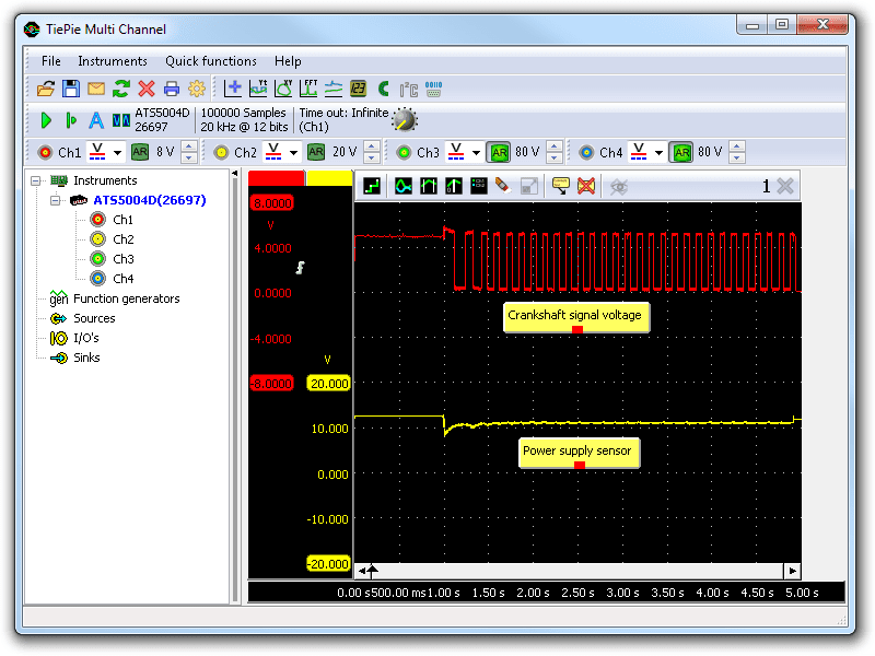
Channel 1 (red) shows the crankshaft sensor signal and channel 2 (yellow) the power supply of the crankshaft sensor. The short spike in the signal at the beginning of the measurement is caused by the switching on of the starter motor. This spike has no effect on the performance of the engine management system because it only reacts to rising and falling edges in the signal. The measured camshaft sensor generates two pules per revolution.
The pattern and number of pulses per revolution can differ from system to system. Systems with (a lot) more pulses per revolution have a higher signal frequency. The used sample frequency may then be too low to make the signal visible. In that case it can be increased via the instrument bar.
The power for the crankshaft sensor in this measurement example is supplied from a system relay. Other cars may have a power supply from the ECU with possibly a different voltage, for example 5 V.
Diagnosis
Signal values may differ on different types of engine control units and crankshaft sensors. Consult ATIS for information on specific engine control units and crankshaft sensors.
The following signal deviations can indicate a problem:
-
No signal:
Cause: back probes have no connection (perform a connection test), no power supply, signal wire shorted to ground, sensor loose or mounted incorrectly, sensor defective -
Signal voltage too high:
Cause: poor or no ground on power supply, sensor defective -
Noisy signal:
Cause: wiring of signal or power supply damaged, poor connection in connector terminals, sensor loose, sensor defective -
Signal shows an offset:
Cause: scope is not set to DC coupling: ,
poor power supply to camshaft sensor, sensor defective
,
poor power supply to camshaft sensor, sensor defective
-
Signal has faulty pattern:
Cause: disk or ring damaged
RELATED PRODUCTS


RELATED ARTICLES
- Camshaft sensor Hall
- With a lab scope a Hall effect camshaft sensor is measured during cranking of an engine. The signal from the sensor is shown and can be downloaded. To help determining whether a Hall effect camshaft sensor is functioning correctly, different possible deviations from the example signal are mentioned along with probable causes.
- inductive crankshaft sensor
- With a lab scope an inductive crankshaft sensor is measured during cranking of an engine, as well as during idling. The signal from the sensor is shown and can be downloaded. To help determining whether an inductive crankshaft sensor is functioning correctly, different possible deviations from the example signal are mentioned along with probable causes.
- Engine stall on Chrysler Voyager
- The engine of a Chrysler Voyager would occasionally stall, only once or twice a day, when running idle. After many attempts, the automotive oscilloscope could capture the vital signals when the engine stalled. Analysis of the signals indicated a defective HALL sensor.
- Xantia refuses to run
- A 1999 Citroën Xantia had a new starter motor fitted, after which it would not run anymore. While cranking it would fire briefly and then die. The car’s battery had been disconnected for the starter motor job. A crankshaft sensor code was logged and thus the crankshaft sensor was replaced, regardless of the good signal. Later the ECM was replaced all with no positive results. The question was if the immobilizer could have reset itself by disconnecting the battery. Proper measuring revealed what the real problem was.
This document is subject to changes without notification. All rights reserved.
The information in this application note is carefully checked and is considered to be reliable, however TiePie engineering assumes no responsibility for any inaccuracies.
Safety warning:
- Before measuring, check that sources of dangerously high voltages are switched off or shielded from contact. Voltages considered to be dangerous are voltages over 30 V AC RMS, 42 V AC peak or 60 V DC.
- Keep a clean working environment when doing measurements.
- This measurement and procedures are a examples / measuring suggestions and are no prescribed protocols.
- TiePie engineering can not anticipate the safety actions that need to be taken to protect persons and appliances. Before starting a measurement, check which safety measures need to be applied.