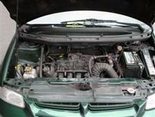
Vehicle information
| Brand: | Chrysler |
| Model: | Voyager |
| Engine: | 2.5L |
| Cylinder count: | 4 |
| Fuel type: | Petrol |
| Motor management system: | Bosch |
Used equipment

Automotive Test Scope ATS5000
2 channel automotive oscilloscope with Arbitrary Waveform GeneratorThe Automotive Test Scope ATS5000 oscilloscope is in this article also referred to as automotive oscilloscope, as Diagnosis Oscilloscope or as lab scope.
Introduction
When the Engine Control Module (ECM) is constantly malfunctioning, it is not difficult to find the cause of the malfunction using relative simple tools, if one has a good knowledge of the system. It is a different story when an error occurs only once in a while. These errors are not always found using a scan tool. Besides, the data transfer rate between ECM and scan tool is usually too low to monitor fast changing sensor signals. In this article, tracing a malfunction in a Chrysler Voyager is described.
Problem description
A garage called about a Chrysler Voyager with a problem. The engine occasionally stalls, usually only once or twice a day. And of course this never happened when a mechanic was driving the car, but only when the owner was driving it. The garage had performed some measurements, but since the malfunction did not appear, there was nothing to measure. After having consulted GMTO it was decided to have GMTO do some examinations with the car using advanced measurement instruments.
The Voyager did not store any fault codes. The problem mostly appeared when the engine was running idle. Just before stalling, the engine was running roughly, appearing to stall a number of times. The owner already pointed out that at those moments the revolution counter dropped to zero.
troubleshooting
At the moment the engine stalled, many things occurred simultaneously, making it hard to find out which function halted first. By recording various signals and making them visible it is possible to see how the problem develops. According to the system schematics, the revolution counter is controlled by the ECM. The signal for the revolution counter depends on the following components:
- Camshaft position sensor
- Engine Control Module
- System relay
- Ignition key lock
- Wiring of the above mentioned components
Checking the position sensor
At first the mechanic examined the signal coming from the position sensor using a diagnosis oscilloscope. The sensor used by the Voyager is a Hall-sensor which is mounted into the distributor. Hall-sensors all switch a signal wire to ground. The voltage on this signal wire is usually 5 V and this can always be measured with a disconnected connector. The Hall sensor also requires a power supply, in this case 8 V. The mechanic happened to see the lab scope image of the sensor when the engine halted. The signal appeared to be a proper square-wave signal until the engine died.
Checking the ignition coil
Then was decided to check the primary side of the ignition coil, using a long record setting on the automotive oscilloscope. This setting provides for measuring data over a longer period of time, one part before and the other part after the trigger moment. Triggering can be one in a few different ways:
- Manually by pressing a key on the keyboard of the computer
- Automatic by applying an appropriate signal to a second measurement channel
- Using an external trigger button
When measuring the signal coming from the ignition coil, the engine started to halt (after running fine for approximately an hour) and the mechanic triggered the lab scope. In the 5 seconds long measurement period, ignition signals of approximately 70 engine revolutions have been stored. Figure 1 shows the disturbances that are visible when the fault occurred. The missing ignition coil control signals are clearly visible in Figure 1 and also the strong variations in the dwell are visible.
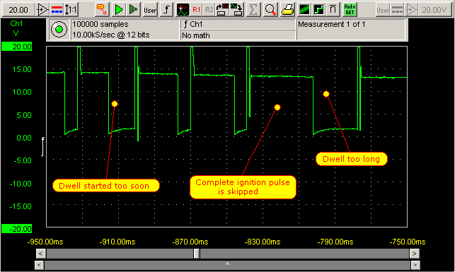
Figure 2 shows the moment where the engine stopped. It is clearly visible that the dwell is started but is not ended.
How to go on?
Based on these measurement results had to be determined what part caused the engine stall. The results showed that ignition pulses were skipped, but the next ignition cycle would appear at the correct moment. That rules out a mechanical problem in the distributor like where the Hall sensor would become loose and shift to a wrong position. Since the ignition is controlled by the ECM and the Hall sensor signal (very important for the timing of the ignition and injector signals) initially appeared to be OK, the ECM itself was suspected. Replacing an ECM is expensive, specially when it turns out that it's not the culprit. Therefore, another measurement on the done on the Hall sensor, to verify the mechanic's observation.
Hall sensor signal
The Hall sensor signal was again measured with the diagnosis oscilloscope, in the long record setting with manual triggering. Then fate struck and the engine would not stall anymore. Automatic triggering had to be selected, using the second channel of the lab scope. The second (trigger) channel had to be connected to a component that is powered in normal conditions, but loses power when the engine stops. The fuel pump is suitable for this task, because it is shut down when the engine stops.
Catching the malfunction
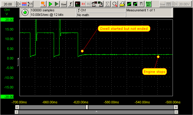
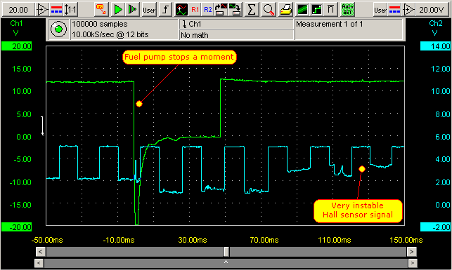
After connecting the automotive oscilloscope, the car had to be driven for a long time, hoping it would stall. Then the engine suddenly stalled, what triggered the lab scope. Finally the Hall-sensor signal in fault situation was recorded and it showed some problems, see Figure 3.
A Hall sensor switches a signal line (usually a 5 V signal) to ground when metal approaches the sensor. This will output a square wave signal, switching between +5 V and almost 0 V. Figure 3 shows a wrong signal of this Hall-sensor where the ground level is clearly fluctuating at a higher level. At some point, the ECM would not recognize a proper square wave signal anymore and would stop controlling the engine. Since the 5 V level appeared to be OK in the lab scope image, the signal wire from the ECM to the Hall sensor had to be giving a proper connection.
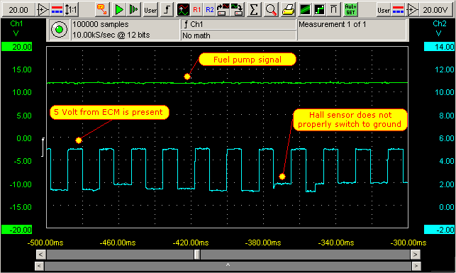
Figure 4 shows the engine halting for a moment and then continue running again (fuel pump went off and on). This triggered the automotive oscilloscope.
Was the fault traced?
No. The fact that the signal did not properly switch to ground could have 2 reasons:
- Bad power supply wiring to the sensor
- Malfunctioning Hall sensor
Before replacing the Hall-sensor, the diagnosis oscilloscope was connected to the power lines of the Hall-sensor. Both the positive and negative terminal of the sensor were measured. Again the fuel pump signal was used for triggering. After a short drive, the engine stalled again and a measurement was performed.
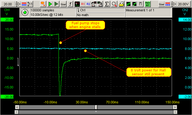
The 8 V power for the Hall sensor remains present when the engine stalls, therefore the Hall sensor itself had to be the culprit. The sensor was replaced and the car has never been back again.
Conclusion
In "once in a while" error situations where no fault codes are present, a diagnosis oscilloscope is indispensable for tracing the problem. Looking back it is easy to say that if this sensor was replaced directly, the fault was solved quicker. But replacing parts randomly, without thorough examination, without knowing if the fault is solved by this, is not good for the customer, nor for the credibility of the garage.
R. Metzelaar