Vehicle information
| Brand: | Ford |
| Model: | Mondeo |
| Engine: | 2.0 L TDdi |
| Engine code: | D6BA |
| Cylinder count: | 4 |
| Fuel type: | Diesel |
| Motor management system: | EEC V |
Used equipment

Automotive Test Scope ATS5004D
4 channel automotive oscilloscope with differential inputs
Measure lead TP-C1812B
low noise differential BNC to banana measuring lead, 3 m
Back Probe TP-BP85
thin and flexible back probeThe Automotive Test Scope ATS5004D is in this article also referred to as automotive oscilloscope, as diagnosis oscilloscope and as lab scope.
Introduction
In modern cars with sophisticated and complex components, troubleshooting requires powerful tools. Most signal lines between components carry modulated signals, signals that (quickly) vary in amplitude to transfer information. Checking the validity of these signals cannot be done using a voltmeter, but requires a good automotive diagnostic oscilloscope, that will show how the signal actually looks like.
This article will show that using a lab scope was essential finding the cause of the problem with a Ford Mondeo 2.0 TDdi which would no longer run.
Problem description
The owner of the car got stranded during a trip abroad with a car that would no longer start or run. Fearing that wrong fuel was tanked, the tank was emptied and the fuel system cleaned. The proper fuel was added but the engine would still not start.
Since wrong fuel was used, damage to the fuel pump was suspected. The high pressure fuel pump was replaced, but the engine still would not start. The garage kept on working in an attempt to solve the problem. In the end, the pump was again replaced and even a new engine was installed in the car, but it still would not run.
Time to proper diagnose the problems in this car, using the right tools.
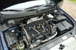
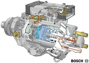
Background information
The 2.0 liter Duratorq Turbo Diesel direct injection engine in this car uses a Bosch VP30 axial-piston distributor injection pump. This pump has its own Electronic Control Module (ECM), which is connected to the engine management ECM by a CAN bus. When operating, fuel is compressed to a high pressure (up to 120 bar) and then distributed to the cylinder(s) that require fuel. The high pressure of the fuel causes the injector to open and fuel is injected in the cylinder. The pump has a special valve in the high pressure area. When it is closed (active state), the pressure is allowed to build up. When it is open (inactive state), the pressure will drop, causing the injector to close and the fuel to flow back to the input side. By activating the valve (closing the return) the moment of injection and the amount of injected fuel (duration of the closed state) can be controlled. The moment of closing the valve and the duration of the closed state are determined by two inputs:
- the exact position of the crankshaft, through a crankshaft position pulse generated by the engine management ECM
- information on the required amount of injected fuel, sent via the CAN bus.
The pump has its own speed and position sensor (a Hall sensor) which signal is used as feedback of the injection advance device to the engine ECM as well as signal when the engine is in "limb home mode" when the crankshaft sensor is defective. Therefore, the connector of this pump has two terminals which carry a 12 V square wave signal.
Measuring
The first thing to check is the fault code memory. It contained two errors:
- U1900 CAN Communication Bus Fault
- U0109 Lost communication with Fuel Pump Control Module
After clearing the error codes, the engine was cranked again, but it would still not start. The same error codes immediately returned. The fuel pump control module receives information about the amount of fuel to inject and the injection timing from the engine ECM by CAN bus, both are essential signals to let the engine run. Therefore these errors are important and not to be ignored.
It was decided to measure the valve control signal (Ch1) and the crankshaft position signal (Ch2) on the pump, as well as the CAN bus (Ch3 and Ch4) on the pump. The CAN bus contains a differential signal, to reduce the influence of external disturbances. Ch3 measured the CAN-High signal and Ch3 measured the CAN-Low signal. The CAN-Low signal is then subtracted from the CAN-high signal by an Add/Subtract I/O in the software, to get the actual CAN signal. The three signals are shown in figure 2.
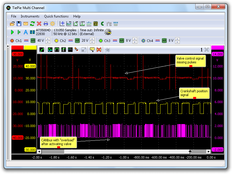
The valve is controlled using a active low signal. Each time the signal is pulled to 0 V, the valve is activated. When the valve is deactivated again, the solenoid in the valve creates a high inductive peak in positive direction, which is normal for this signal and can be ignored.
There is a repeating pattern visible of two valve activations and then some idle time. The engine has four cylinders so one would expect a repeating pattern of four valve activations, there is something wrong in the valve activation signal. It is also visible that after each second valve activation, a lot of activity is visible on the CAN bus. The crankshaft position signal appears to be OK. Apparently something goes wrong when the valve is activated, causing the pump ECM to stop function properly and losing CAN communication.
Timing issue?
Thinking that this might be caused by a timing issue, another measurement was performed. Ch1 was connected to the valve control signal, Ch2 to the pump advance signal of the pump and Ch3 to the crankshaft signal of the engine. The measured signals are shown in figure 3.
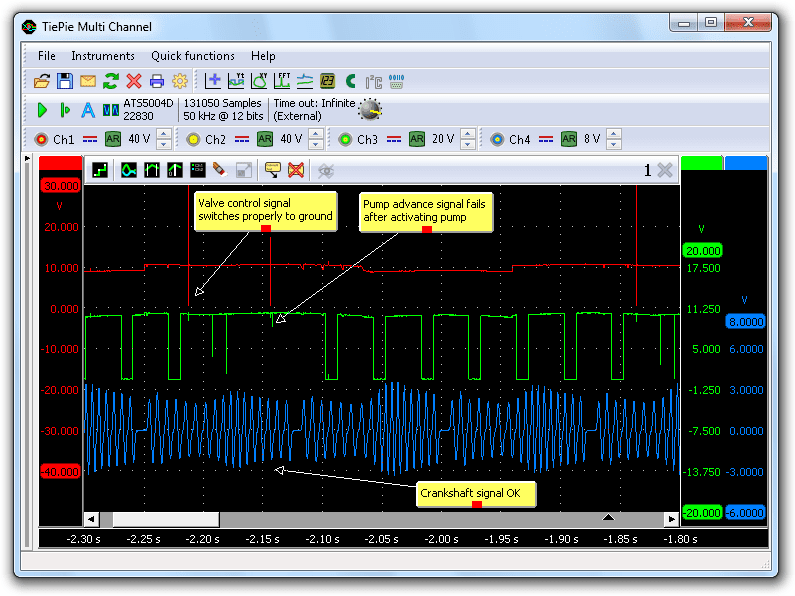
It is clearly visible that the pump advance signal fails after each valve activation. This signal is generated in the pump ECM. The fact that it fails after activating the valve, reinforces the idea that activating the valve causes the pump ECM to malfunction, not a timing issue.
Checking the valve
The valve is activated by driving a current through a solenoid. When the valve control signal is pulled low, a current starts flowing through the solenoid. This solenoid has a low resistance (0.2 to 0.3 Ohm), causing a high current to flow. A problem may occur when the control signal is not pulled to zero properly, but in this situation the signal was pulled low enough. Therefore, the power signal to the valve and the ground signal of the pump were measured.
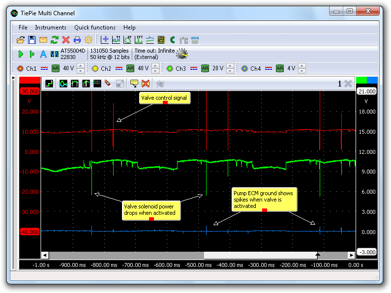
Figure 4 shows the measurement on the valve control signal (Ch1, top), the valve solenoid power (Ch2, middle) and the pump ECM ground (Ch3, bottom). All were measured against the battery ground, to be able to detect voltage losses.
When the valve is activated, the valve solenoid power drops significantly. This is barely visible due to the short duration of the voltage drop. The pump ECM ground also shows a little spike, but that remains small.
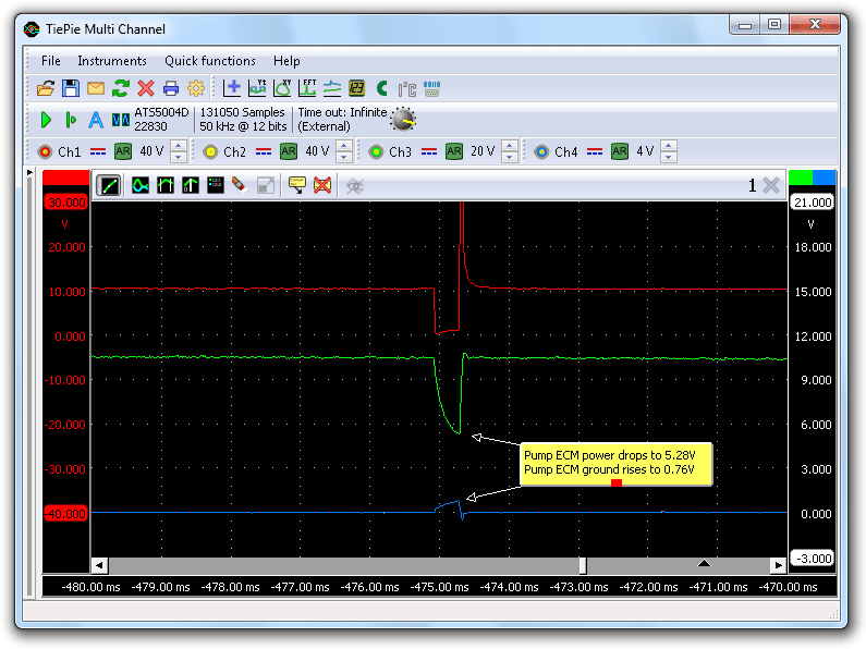
The measurement was repeated and this time the pump ECM power was measured instead of the valve solenoid power. The pump ECM power showed the same voltage drop, indicating that this drop was caused outside the pump. Zooming in on a single valve control pulse shows exactly what happens, see figure 5. When the current flows through the valve solenoid, the ECM power drops shortly from 10 V to 5.28 V and at the same time the ground level rises to 0.76 V. That leaves only 4.5 V to power the ECM. The ECM cannot operate on such a low voltage and stops working. That explains why valve control pulses were missing and the CAN bus communication was lost.
Cause
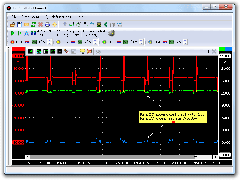
There had to be a problem in the positive power to the pump ECM. According to the wiring diagram, the power to the pump is controlled by a relay. A bad contact in this relay or the wiring to the relay had to cause the large voltage drop. The wiring and the relay were bypassed by connecting a wire from the pump ECM power terminal directly to the positive terminal of the battery. The engine started immediately and the signals looked a lot better now (see figure 6).
Solution
Now the relay and corresponding part of the harness was bypassed, the problem was gone, indicating that one of them had a bad contact, causing the voltage drop that shut down the pump ECM. The garage was advised to check and repair or replace the wiring harness and the relay.
Conclusion
Properly diagnosing a problem using the right tools can make a huge difference. This car probably never required a new fuel pump and engine, just a new relay or a piece of wiring harness repaired. It would have saved a lot of time and money.
If the pump power was measured using a multimeter, it would have indicated a voltage level of approximately 10 V, which would not have alarmed anyone. However, by measuring the power using a good automotive oscilloscope like the Automotive Test Scope ATS5004D, the short but significant power drops on the pump ECM power became visible, leading to the cause of the problems in this car.
R. Metzelaar