Vehicle information
| Brand: | Kia |
| Model: | Carnival |
| Year: | 2000 |
| Engine: | 2.5L V6 |
| Engine code: | KV6 |
| Cylinder count: | 6 |
| Fuel type: | Petrol |
| Motor management system: | Siemens K62 |
Used equipment

Automotive Test Scope ATS5004D
4 channel automotive oscilloscope with differential inputs
The Automotive Test Scope ATS5004D is in this article also referred to as automotive oscilloscope, as Diagnosis Oscilloscope or as lab scope.
Problem description
A customer of GMTO was confronted with a problem of a KIA Carnival. This car had a specific problem with the Anti-lock Braking System (ABS). It looked like a problem that easily could be solved, because the problem always occurred when the speed of the car was above 130 kilometers per hour. The problem showed itself by the ABS warning light that went on every time the car came above 130 kilometers per hour. This makes it normally easier to trace down the cause of the problem. The KIA can be read out with serial reading instruments and also with use of flashing codes. The ABS warning light indicated that there was a fault with the left wheel sensor, so the fault appeared to be solved easily. The sensor was replaced and the car was ready to go. But that was not the fact. The ABS warning light still went on when the car got above 130 kilometers per hour. The new installed sensor was also replaced, thinking that this sensor also was defective. Distributors of these parts must get mad from this needless actions, because they are the ones who get all guarantee claims.
ABS wheel sensor
The wheel sensors of Anti-lock Braking Systems work according a familiar principle that is also used by crankshaft and camshaft sensors. The rotating part, in this case the wheel, has a disc with metal teeth. The sensor is equipped with a coil and a permanent magnet. A coil has the characteristic feature that it produces a voltage when a moving magnetic field is present. In case of a not rotating wheel there is a permanent magnetic field, but because it is not moving, it does not affect the coil. With this wheel sensor, it depends on the presence or absence of metal in front of the sensor. If there is no metal in front of the sensor, the magnetic force lines from the permanent magnet will go from north to south in a specific way. These magnetic force lines also go through the coil windings. With a rotating wheel, a metal tooth will come in front of the sensor in the course of time. The magnetic force lines then completely change, also in the coil of the sensor. This change in the magnetic field produces, only once, a voltage peak. Let's assume that this is a positive voltage. This voltage is thus produced in the transition from non-metal to metal in front of the sensor. If the metal stays in front of the sensor (the wheel has stopped again), the voltage drops to 0 V. The opposite will happen if the wheel keeps rotating and the metal tooth moves away from the sensor. A negative voltage pulse is then produced in the coil of the sensor, because the magnetism is returning back into its previous state. When the wheel is rotating the teeth appear and disappear from the sensor continuously. This produces a continuous change in voltage. The distance between the sensor and the metal teeth is very important, because a larger distance between those two parts produces a smaller magnetic change and thus producing a lower voltage. In this case the margin is between 0.1 and 1.5 mm.
Sensor signal
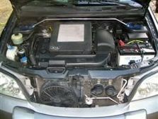
Figure 1 shows the signal of the ABS wheel sensor at a speed of 30 kilometers an hour. The 'peak to peak' value of this alternating current is approximately 3 V. Typically for this signal is the offset in the signal. The signal is not alternating around 0 V, but just above the 0 V (0.8 V). This offset can be measured when the wheel is not rotating. Nowadays this offset voltage is used for diagnostic reasons, so that the Electronic Control Module (ECM) can better recognize a short-circuit with ground.
Measuring
After installing the second sensor, the ABS warning light still went on. A multimeter was used to measure the generated voltage (always set the meter to AC) and to check the wiring using the Ohm meter setting. Both measurements showed normal results and a mystery was born. The car was then brought to GMTO for investigation. In this case, GMTO directly started measuring with a lab scope, because reading the fault code memory and examining the retrieved data was already done by the garage and offered no solution to the problem.
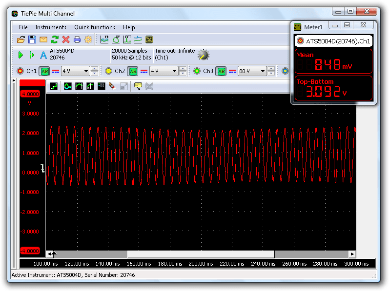
In situations like this, GMTO specialists always use the Automotive Test Scope ATS5004D for measuring signals. A function inside the lab scope is used, which continuously measures the input signals, but only captures the signal and transfers them to the computer when the operator triggers the diagnosis oscilloscope. The large internal memory allows to make a long measurement that contains lots of information. After doing these measurements it got clear for GMTO what the problem was. See figure 2.
Cause traced
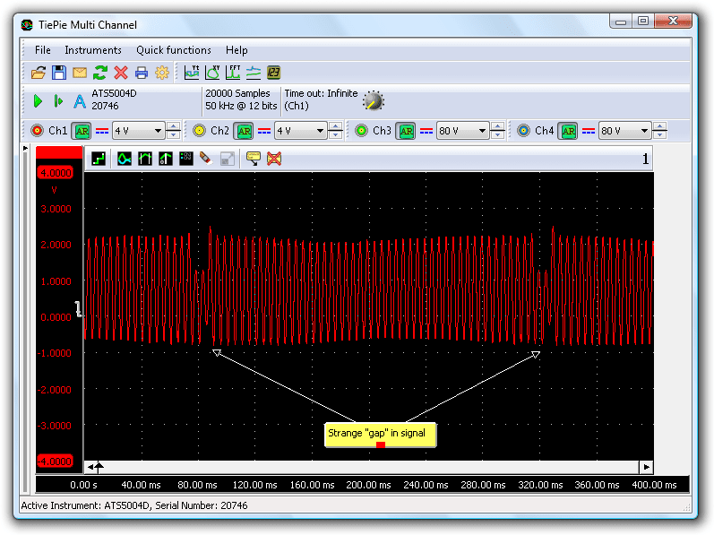
Very typical in the automotive oscilloscope picture are two strange anomalies in the signal, at two places. Since these anomalies appear in a fixed pattern, it cannot be a problem with the electronics, but the cause of the problem should be found at the mechanical side of the car. The repetition is caused by the constant reappearing of the ABS disk teeth in front of the sensor. The signal also shows a little amplitude variation. That is not uncommon, it is caused by the fact that the ABS disk is not perfectly round. After the conclusion that it had to be a mechanical problem with the ABS disk, the disk was examined and there the problem showed up. Figure 3 clearly shows the broken teeth on the disk.
The only question that remained was why the fault was only reported when the speed was above 130 kilometers per hour. The answer to this question was quickly found when the signal was measured at this high velocity, see figure 4.
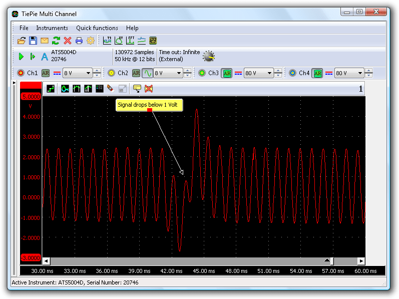
It shows that the amplitude drops when the broken teeth pass the senor. At low speed, the peak to peak amplitude when the broken teeth passed the sensor was 1.5 V. In the same situation, but then at 130 kilometers per hour, the voltage dropped to below 1.0 V. This drop in amplitude is certainly caused by the broken teeth on the ABS disk.
Conclusion
The ABS ECM sets a limit on the voltage of the signal coming from the ABS wheel sensors. This can be a fixed value, where the signal always must be above or under a defined value. but it is also possible that this limit is set dynamically, depending on the speed of the car. So it can be that at a lower speed the limits are less strict then at a high speed. In this case it is clear that the ABS ECM did not recognize some of the teeth at an amplitude that was not above 1 V. Therefore an irregularity was found at the disk. The ECM generated a fault code and switched off the ABS (light goes on). The ABS system can not function properly if faultily information is received from the sensor which increases the possibility of making a wrong brake decision. The broken teeth were initially repaired with liquid metal and the problem was solved. In a later stage, the ABS disk was replaced by a new one.
R. Metzelaar