Vehicle information
| Brand: | Renault |
| Model: | Megane |
| Year: | 1998 |
| Engine: | 1.6 L |
| Engine code: | K7M |
| Cylinder count: | 4 |
| Fuel type: | Petrol |
| Motor management system: | Siemens Fenix 5 |
Used equipment

Automotive Test Scope ATS5004D
4 channel automotive oscilloscope with differential inputs
Measure lead TP-C1812B
low noise differential BNC to banana measuring lead, 3 m
Back Probe TP-BP85
thin and flexible back probe
The Automotive Test Scope ATS5004D is in this article also referred to as automotive oscilloscope, as diagnosis oscilloscope and as lab scope.
Introduction
Intermittent problems in cars can give garages a hard time, especially when their only diagnosis device is a fault code scanner and no codes are stored in the car. Finding the cause of the problems is then a matter of checking all possibly related systems in a structured way. Knowledge of the automotive systems is important, as well as the basic principles of electrical engineering, like e.g. Ohm's Law. And last but not least, using the right tools, a good automotive diagnostic oscilloscope is indispensable.
Problem description
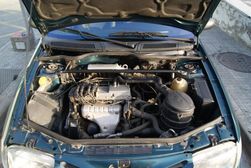
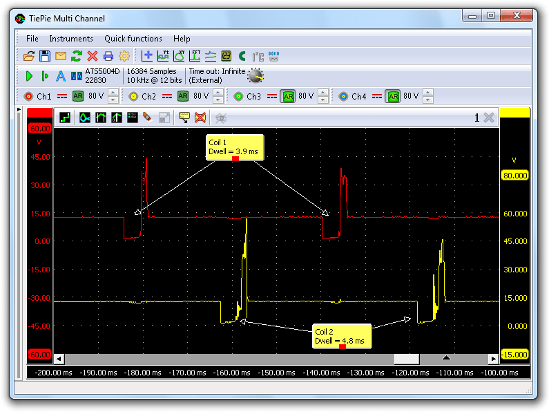
A garage is dealing with a 1998 Renault Megane 1.6 L with K7M engine with a dual fuel system, both petrol and LPG. Every now and then, the engine hesitates, both on petrol and on LPG. The garage checked components that are used in both situations, like e.g. the crankshaft sensor signal and the ignition. This engine uses DIS ignition, where two spark plugs are in series connected to a single coil. Both fire at the same moment, where one of the two fires in the exhaust stroke (wasted spark). This system does not require a distributor, making it simpler and easier to maintain, as no mechanical parts wear out. While measuring the primary ignition signals for the two coils, they found a difference between the two ignition signals. One signal showed a much longer dwell than the other signal, as visible in figure 1.
A longer dwell can indicate a too low supply voltage. The Electronic Control Module (ECM) will then increase the dwell to allow the coil a longer time to accumulate enough charge for a spark. It can also indicate a defective ECM. Without knowing that the ECM was indeed defective, it was replaced, hoping that would solve the problem. It did not and GMTO was then consulted to find the cause of the problem.
Measuring
troubleshooting always starts by bringing the car in the problem situation and measuring the vital signals at that moment. The automotive oscilloscope was connected to an ignition signal (Ch1) and an injection signal (Ch2). The oscilloscope software was setup to respond to pressing a manual trigger button and to store the signals, both before and after pressing the button. The car was then driven until the engine failed, at that moment the manual trigger button was pressed and the two signals were stored, even from 2.6 seconds before pressing the button.
Both ignition and injection signals are low active signals. To activate the ignition or injector, the signal is pulled low, to 0 V. Both signals drive an inductive load (a coil or solenoid). When the signal goes high again, the current stops flowing, which results in a high inductive peak on the signal. This is normal behavior and can be ignored.
Both ignition and injection signals fail at the same time. A zoomed in view of the signals at the moment of failure is shown in figure 2. Since both signals failed at the same moment, the crankshaft signal was measured as well at a later time, but this signal stayed OK when the problem occurred.
Another strange thing that is visible in figure 2 is the slope in the injection signal. Normally the signal remains on supply voltage level between two pulses, but the signal slowly drops during the problem situation. This can indicate a power supply problem.
Supply power failure?
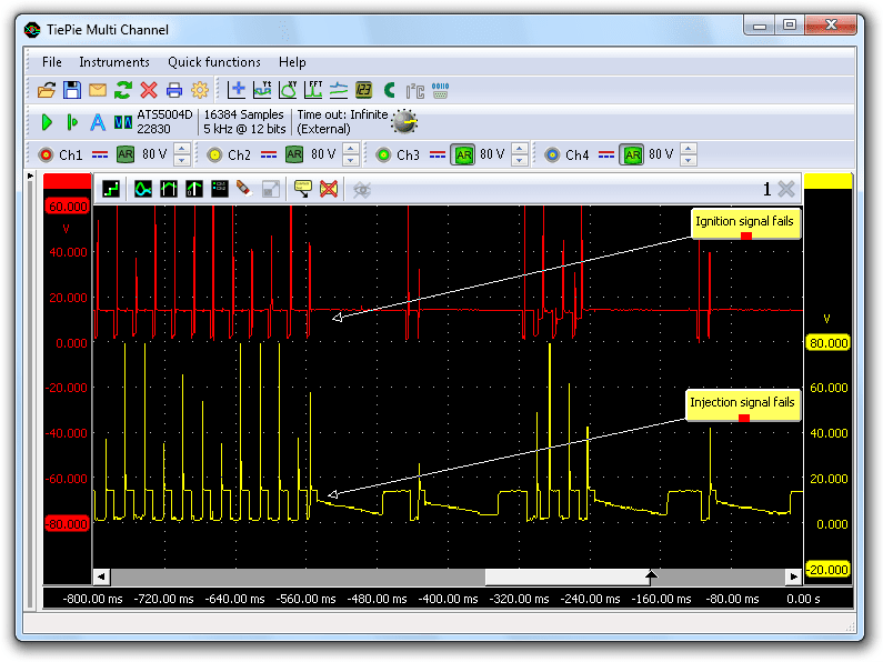
The supply power for the ECM was then measured. This signal is controlled by the system/pump relay, one relay for ECM, injectors, fuel pump and some other components. Figure 3 shows the measurement of the supply voltage.
At the moment the problem occurs, the voltage level drops linearly. This indicates a power failure. The fact that the voltage does not directly drop to zero but slowly decreases, is caused by the fuel pump. It is still spinning and starts functioning as a generator.
Figure 3 also shows a measurement of the system/pump relay control signal. It is an active low signal: the relay is activated when this signal is pulled to zero. During the problem the control signal fails and goes high, deactivating the relay. Just before the signal fails, it increases a bit. A similar increase is seen again later in the signal.
Also visible in this signal are many short pulses. After examining the wiring diagram, these turn out to be pulses to drive the rev counter. An extra measurement showed that the frequency of the pulses is related to the rpm of the engine. These pulses are too short to deactivate the relay.
The increases in the ground signal indicated that this could be a grounding issue. When a ground connection fails, the voltage loss over the ground connection becomes too high, causing signal levels from various sensors becoming too high. One of these sensors can be the throttle position sensor. Its signal was measured and showed a problem, see figure 4.
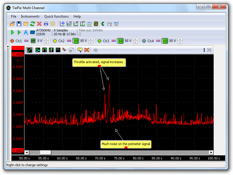
The signal is very noisy and it is constantly too high. The "fully closed" voltage for this sensor signal is 0.5 V, while in this measurement it is continuously higher than 1 V.
Cause and solution
As mentioned before, a bad ground connection can increase sensor output levels. The ground connection of the throttle position sensor was then measured against the battery ground, see figure 5.
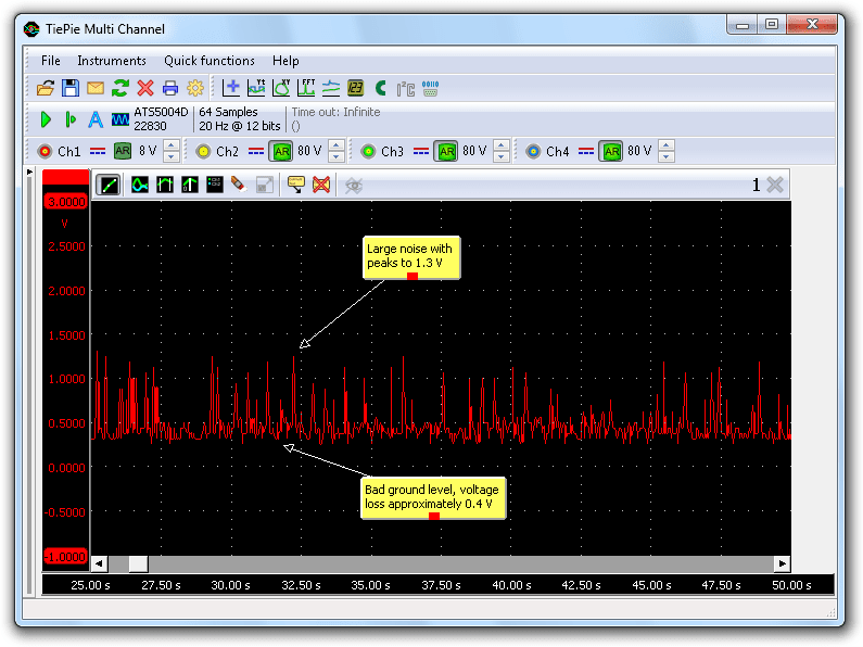
The ground signal for the throttle position sensor shows the same noise and is too high, clearly indicating a bad ground connection. All ground terminals were checked and one ground terminal on the engine turned out to be the culprit. The connection was cleaned and firmly connected. This solved the problem and the engine was now running fine again.
Conclusion
The engine failures were probably caused by the ECM stopping due to failing power. Short intermittent power failures are hard to find when the right tools are not available. A voltmeter or multimeter will not show the short glitches or the noise, because it is far too slow for that. A proper automotive diagnostic oscilloscope like the Automotive Test Scope ATS5004D does show the short power interruptions and the noise on the signal.
R. Metzelaar