Vehicle information
| Brand: | Jeep |
| Model: | Cherokee |
| Year: | 2002 |
| Engine: | 2.5L CRD |
| Engine code: | R 425 |
| Cylinder count: | 4 |
| Fuel type: | Diesel |
Used equipment

Automotive Test Scope ATS5004D
4 channel automotive oscilloscope with differential inputs
Current clamp TP-CC80
0 - 80 A input rangeThe ATS5004D oscilloscope is in this article also referred to as automotive oscilloscope, as diagnosis oscilloscope and as lab scope.
Problem description
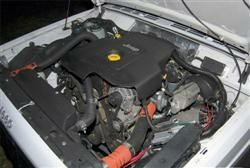
A 2002 Jeep Cherokee 2.5 CRD diesel with 60.000 km on the clock would not start properly. While cranking, it first appeared the engine would start but then for several revolutions it would do nothing at all. After relatively long cranking, the engine would eventually start. The owner wanted this problem solved and went to his local garage. The garage checked and replaced several components, but the problem remained. The car was then brought to a Jeep dealer. The dealer could also not solve the problem and concluded that the engine was worn and needed to be replaced! For a second opinion, GMTO was contacted.
Common Rail injection
A common rail injection system is sensitive for fuel pressure. Wear of the high pressure pump or pressure regulating valve, or a defective pressure sensor can cause problems like this car has. A measurement of the signals of these components will immediately give a good indication of the condition of these components.
A measurement of the pressure regulating valve signal and the pressure sensor with an automotive oscilloscope will show the relation between the two. An extraordinary duty cycle (almost 0% or 100%) combined with a normal signal amplitude on the pressure sensor (or vice versa) will indicate there is something wrong in this circuit. When the pressure sensor generates a signal of e.g 2.0 V at a pressure of 150 Bar (actual pressure) while it should be 1.0 V, the ECM will set the duty cycle for the pressure regulating valve control signal to a different value than it should be. As a result, the actual pressure will get a lower value than intended. When we assume that a pressure regulating valve is "low active" and will release the pressure in active state, the duty cycle of the control signal will be significantly higher than normal.
ATIS of GMTO contains a large database with measurement examples of almost all components in the motor management system, arranged by brand and model and also universally applicable. Each example consists of an automatic setup of the automotive lab scope together with loading of corresponding example waveforms. Explanative text with photographs show where and how to connect the automotive diagnostic oscilloscope to the component(s) under test. The user can simply select the correct measurement and perform the measurement, without worrying about how to setup the automotive oscilloscope.
The first measurements that were done using the Automotive Test Scope ATS5004D indicated that these signals were stable and correct. It is best to measure the actual pressure, but that is not always easy to do, because of the accessibility of the components and the availability of a pressure test point. Although nothing pointed to a failing crankshaft sensor or camshaft sensor (the engine initially appears to start while cranking), it was decided to measure the signals from these sensors too, just to rule out any possible cause. Figure 1 shows both signals clearly.
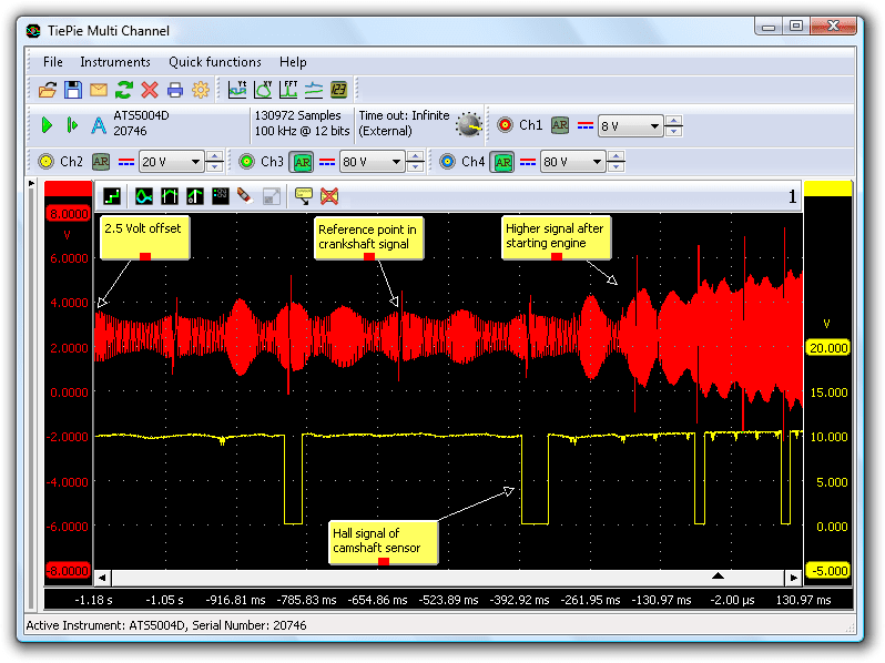
The inductive crankshaft sensor has a coil that will induce a positive and negative peak when a tooth of the crankshaft passes the sensor. Figure 1 shows that the signal is not symmetrical around 0 V, but around 2.5 V. The signal has a 2.5 V offset. Many systems use an offset to allow for better self diagnosis. It appeared the offset was normal. The HALL camshaft sensor switches perfectly to ground, showing no problems.
Driving the injectors
After these measurements, it was required to check the injection control signal. To get a better view of the injection pattern, it is advised to measure it together with the crankshaft sensor signal. A normal common rail injector is driven in two stages, one being the pre injection.
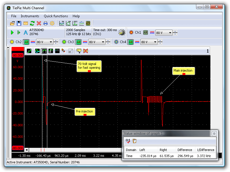
Figure 2 shows the injection control signal of a full cycle, including the pre injection. Due to the way the injector is driven, the automotive diagnostic oscilloscope input is connected directly to both injector wires and not to one wire and ground. The positive terminal of the injector is connected to a DC voltage of approximately 80 V. The negative terminal of the injector is connected to ground in a pulsating way, because of the high current that will flow through the injector.
After each pulse, a high negative inductive peak of approximately 40 V will appear, due to cutting the current through the injector. In this situation, the pre injection only lasts 296 µs (0.000296 s). Only a very small amount of fuel will be injected in the cylinder. The duration of the main injection lasts longer, depending on the demand.
A current clamp can be used to measure the current through the injector. This has the advantage that both timing and conductivity of the injector can be checked. A too low current will indicate contact resistance or a defective injector coil. Figure 3 shows a current measurement on an injector.
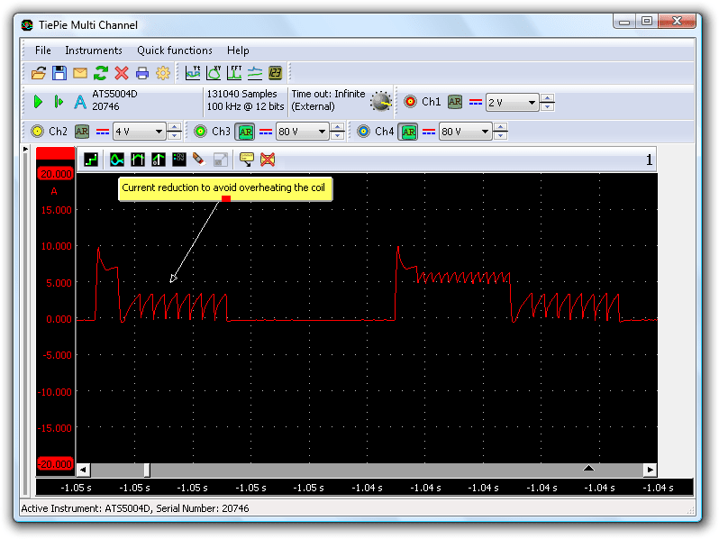
With a voltage of 80 V on the coil of the injector, the current increases rapidly to 10 A. This ensures a very short time to open, which is required since the injector will only be open for 296 µs. After this short current peak, the ECM will intermittently switch the current off and on, to avoid overheating of the coil. This is seen in the smaller current peaks after the initial large peak. Due to the inertia of the injector, it will remain open and the fuel injection will continue. Figure 3 also shows the main injection, a short moment later. Again the current pulses to avoid coil overheating are visible.
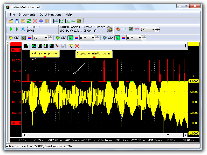
Figure 4 shows the combined measurement of injector signal and crankshaft signal. It is clearly visible that while cranking, at first a single injection is seen and then a few revolutions the injections are not seen. This measurement covers a longer time, but was nevertheless measured using a high sampling rate. This is possible because of the long record length of the automotive oscilloscope. It ensures that when zooming in, a crisp signal with lots of details can be seen.
Looking at the details
Initially, the individual signals all looked correct. The current to the injector as well as the timing of the injection were correct. The crankshaft signal also looked correct and was higher than 0.5 V during cranking. After zooming in (figure 5) we could get a better view on the signals.
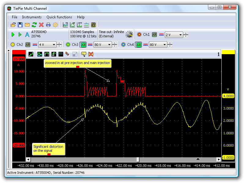
We noted a signal disturbance on the crankshaft sensor signal. This disturbance occurred at the same moment that the injector signal was present and is caused by interference of the injector signal on the crankshaft signal. After analyzing several measurements of starting attempts, it was observed that when this distortion happens exactly between the positive and negative peak of the crankshaft signal, the ECM will stop driving the injectors for some time.
Apparently, the ECM recognizes this disturbance as reference point in the crankshaft signal and then stops injection, because the injection timing pattern no longer matches with the crankshaft pattern. When, after some more cranking, the disturbance would not fool the ECM, the engine would start.
Crankshaft sensor defective
At first was tried to move the crankshaft sensor wiring away from the other wiring, to reduce the interference but that did not help. Despite that the crankshaft signal appeared correct and the resistance value of this sensor was within the limits, it was decided to replace the crankshaft sensor. After installing the new sensor, the engine started immediately.
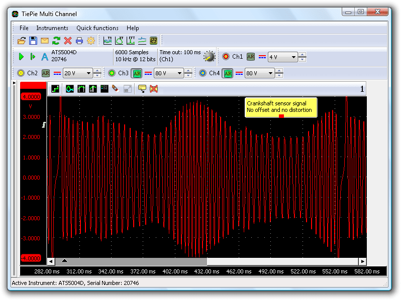
A measurement on the new sensor (see figure 6) showed that this sensor had no offset, but the generated signal was symmetrically around 0 V. Apparently something internally in the sensor was wrong, causing the offset and the sensitivity to the interference of the injector signals.
R. Metzelaar