Vehicle information
| Brand: | Toyota |
| Model: | MR2 |
| Year: | 2000 |
| Engine: | 1.8L 16V VVT-i |
| Engine code: | 1ZZ-FE |
| Cylinder count: | 4 |
| Fuel type: | Petrol |
| Motor management system: | TCCS |
Used equipment

Automotive Test Scope ATS5004D
4 channel automotive oscilloscope with differential inputs
Current clamp TP-CC80
0 - 80 A input rangeThe Automotive Test Scope ATS5004D is in this article also referred to as automotive oscilloscope, as diagnosis oscilloscope and as lab scope.
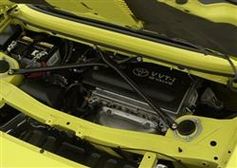
Problem description
A GMTO customer had a Toyota MR2 with a bad running engine for repair. Initially the car had suffered engine damage and the engine was replaced by another, revised engine. At first, all seemed normal but after a few weeks the replacement engine started running bad. The fault code scan tool showed code P0304.
P0304 : Cylinder #4 Misfire Detected
A misfire can be caused by the engine running too lean. Possible causes for the engine running too lean are a vacuum leak, malfunctioning injector(s), wrong fuel pressure. To find the culprit, the garage started swapping components between cylinders. This car has an ignition system with an individual coil per cylinder. At first, the coil for cylinder 4 was swapped with the coil for another cylinder, but the problem remained with cylinder 4. Then the injector of cylinder 4 was swapped with another cylinder, but again, the problem remained with cylinder 4. The garage then contacted GMTO for assistance.
Measuring with a diagnosis oscilloscope
By this time, the engine was running bad permanently, one or more cylinders had to cause this problem. Using the automotive oscilloscope, a compression test was executed.
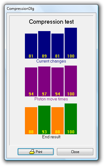
The result in figure 1 shows that the engine is not perfect, but the compression differences were not that big that it would explain this engine problem.
The Lambda sensors
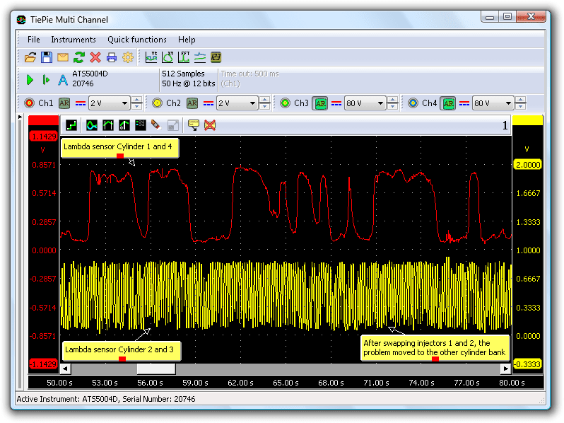
Combustion mixture problems can also be measured using the lambda sensor. This engine contains two lambda sensors, one controlling the mixture for cylinders 1 and 4 and one lambda sensor for cylinders 2 and 3. Therefore, when looking at the combination of lambda sensors / injectors, this engine can be treated as two 2 cylinder engines.
Both lambda sensors were measured and it was clearly visible that the combustion of cylinder 1 or 4, or both, has a problem. In figure 2, the upper scope signal (cylinders 1 and 4) shows a fast fluctuation on the lambda sensor signal. The lower scope signal (cylinders 2 and 3) shows the lambda sensor signal controlling the mixture for cylinders 2 and 3. The lambda signal for cylinders 2 and 3 looks normal, but the signal for cylinders 1 and 4 certainly not.
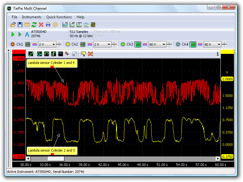
What is happening here? Due to a misfire, there was only a partial combustion or even no combustion at all and oxygen is left in the cylinder. During the exhaust stroke, this oxygen flows past the lambda sensor, causing an output voltage of (almost) 0 V. In figure 2, it is visible that when cylinders 1 and 4 are in their "rich" cycle (lambda = 0.8 V), the output of the lambda sensor intermittently drops to a much lower value. Each cylinder stroke with the bad combustion causes a drop of the lambda signal. This was a good starting point for further analysis.
The injectors
After having checked for leakage, the driving voltage and current for injector 4 were measured. When performing diagnosis measurements on injectors, the voltage at the negative terminal of the injector is measured, as well as the current, using a current clamp. ATIS has a pre defined setup for this measurement, so the instrument is fully setup with a single click. Nothing strange appeared in this measurement. Channel 2 shows the voltage over the injector. The high peak is the induction peak over the coil, caused by the fact that the current was cut. This voltage can become quite high, but because the input was set to the 40 V range, the measured signal is clipped at 40 V. The width of the pulse at the top shows that the actual voltage must have been much higher than 40 V.
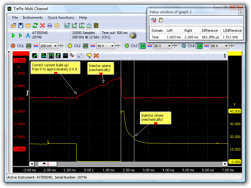
The opening times of the other injectors were measured as well and then injector 1 showed a pattern different from the other injectors.
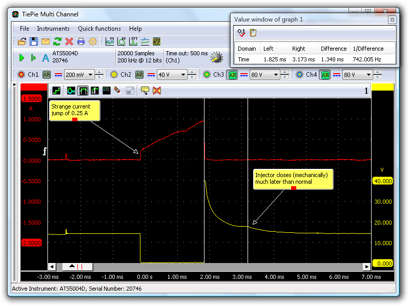
Three anomalies are visible:
- The current flowing through the coil of the injector shows a current jump of 0.25 A. This is impossible with a current flowing through a coil, the current should start at 0 A and then increase linear.
- The induction pulse is too low. This pulse usually becomes approximately 80 V, but this pulse barely reaches 40 V.
- A too long closing time. The closing moment of a valve (in this case the injector) is visible in a small "bump" in the voltage pattern after the induction peak. For this injector, the closing time is more than twice the time for a normal injector (1.3 ms versus 0.66 ms)
These are enough reasons to reject injector 1.
The cause
A too fast current increase and a too low induction peak can be caused by a parallel resistance over the injector terminals. This resistance also causes that the induction pulse energy forces the current through the injector to flow longer, resulting in a longer opening time. Bad injector 1 is significantly longer open than the other injectors. That results in much more fuel in cylinder 1 than in cylinder 4. The ECM responds by reducing the opening time for both injectors (they are both monitored by the same lambda sensor) to get a proper combustion in this cylinder bank. That fails, because the amount of fuel for cylinder 4 then becomes too low, resulting in a too lean mixture. As a result, cylinder 4 misfires, which is detected by the ECM and appointed as culprit. The diagnosis problem is born and the garage fully focused on cylinder 4 while cylinder 1 was the culprit.
Verification
To verify that indeed injector 1 caused the problem, first signals for the injectors for cylinders 1 and 2 were swapped.
The abnormal oscilloscope images for voltage and current remained at cylinder 1, ruling out the ECM as possible cause. Swapping injector signals can be done for a short while, for this purpose. It will obviously disturb the lambda system completely.
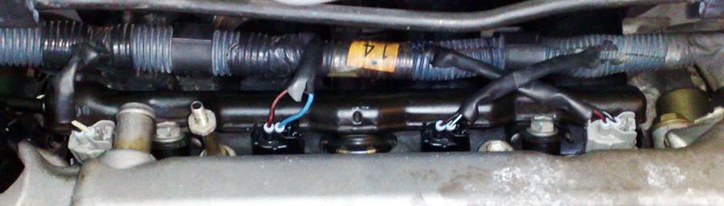
Finally, the injectors for cylinders 1 and 2 were swapped. The bad injector is now in the other cylinder bank. The signals for the two lambda sensors changed, the signal for cylinders 2 and 3 now became bad.
This leaves no doubt that the injector for cylinder 1 is malfunctioning. A coil resistance measurement showed that injector 1 has a resistance of 14 Ohm, 2 Ohm lower than the other injectors.
Conclusion
Diagnosing a problem can be a difficult task. And when a fault code scan tool points in the wrong direction, it can become very difficult. Exact measuring with an automotive oscilloscope and a good knowledge of the systems and components remains crucial. Swapping components to find the cause of the malfunction can be misleading. In this case, no components for cylinder 1 were swapped, so the problem remained. The garage replaced the malfunctioning injector with a new one, resulting in a good running engine.
R. Metzelaar