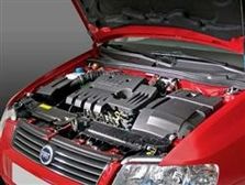
Vehicle information
| Brand: | Fiat |
| Model: | Stilo |
| Cylinder count: | 4 |
| Fuel type: | Petrol |
Used equipment

Automotive Test Scope ATS5004D
4 channel automotive oscilloscope with differential inputs
The Automotive Test Scope ATS5004D is in this article also referred to as automotive oscilloscope, as diagnosis oscilloscope and as lab scope.
Problem description
A Fiat dealer was trying to repair a Fiat Stilo which did not start in 50% of the attempts. In case the engine did start, it ran normal, according to the mechanic. The car was checked with Fiat test equipment and fault code scanners. Several codes were found, but none of them appeared to be related to the problem. The mechanic who worked on the car suggested that the CAN bus might have a problem. This appeared reasonable, because all information disappeared from the dashboard during cranking. In many cases, the electronics of the ignition key transponder system is located in the dashboard, so this could cause the engine not starting.
The Fiat dealer contacted GMTO for advice. GMTO advised to measure the CAN bus signals with a diagnosis oscilloscope during cranking. The measured signals were sent to GMTO and analyzed there. They can be seen in figure 1. It looks like the CAN bus signals are strongly distorted. However, the CAN bus carries a differential signal to reduce the possibilities of errors through external interference. The CAN bus signal appears to be distorted, but is correct, as can be seen in the difference signal created by subtracting the CAN-L signal from the CAN-H signal.
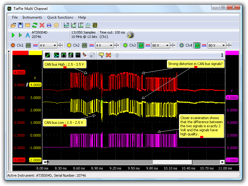
The no starting problem was most probably not caused by CAN bus problems. It was decided to bring the car to GMTO.
First a new battery
When the car arrived at GMTO, more tests on the dashboard were performed. It appeared that the power of the dashboard dropped to below 6 V, during cranking. It turned out that the battery was bad and a new battery was installed. This solved the dashboard problems, but the car still wouldn't start.
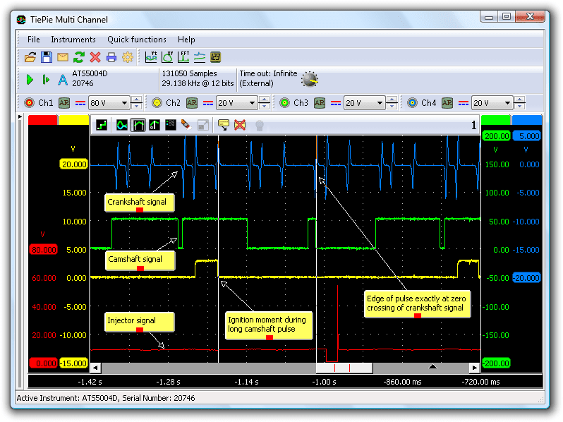
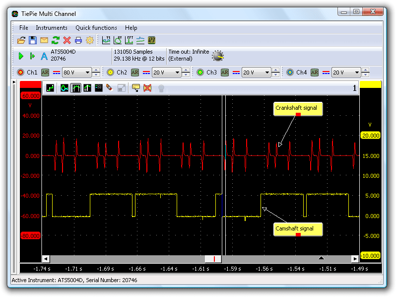
The next step was to measure the most important input signals for the ECM to generate ignition and injection signals: the camshaft sensor signal and the crankshaft sensor signal. Also the ignition pulse to the coil and the injection pulse were measured. This was measured with a 4 channel differential automotive oscilloscope. Using a differential oscilloscope gives the advantage that the cables can be connected in any way, without the risk of creating short circuits via the instrument. All required signals appeared to be present (see figure 2).
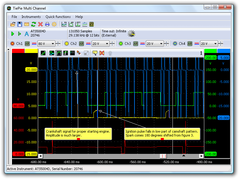
But why would the car not start? The car was cranked and the signals were measured until the car started (figure 3).
The two measurements were then compared.
Analyze four signals
The following signals are visible in the automotive oscilloscope screen:
- The upper most signal is the inductive crankshaft sensor signal. This sensor always generates an alternating signal. The fly wheel has teeth, which pass the sensor at close distance as the fly wheel rotates. When a tooth approaches the sensor, the voltage increases in positive direction. When the tooth moves away from the sensor again, the voltage becomes negative. The signal for the Fiat Stilo is a bit remarkable, as it has two "pulses" shortly after each other, then a short delay and then another single pulse. This pattern repeats twice for each revolution of the crankshaft.
- Signal two is the camshaft sensor signal. This sensor is a HALL sensor, which switches the output to zero when activated. Therefore this sensor always generates a square wave signal, in this case between 0 and +5 V. Since the camshaft rotates at half of the speed of the crankshaft, the ignition pulse for a cylinder must appear once per camshaft revolution.
- Signal three is the pulse that is sent to the ignition module. At the rising edge of the pulse, current will start flowing through the primary coil. The falling edge is the ignition moment, where the current in the coil is cut.
- Signal four is an injector signal.
Sparks at wrong moment
The fault was easily spotted, the ignition and injector pattern was completely shifted between the two measurements (figures 2 and 3). After some measuring and calculating was discovered that in the non starting situation (figure 2), the ignition moment and injection moment were shifted 180 degrees compared to the starting situation (figure 3). This means that the spark plug would spark in the lowest position of the piston.
See figure 3 for the correct injection and ignition pattern. In figure 2 the ignition pulse is generated when the camshaft signal has its second long higher part of the pulse (engine not running). In figure 3 this pulse is situated in the first long lower part of the pulse (correct position and engine running).
Timing error between camshaft and crankshaft
Now the cause of this fault had to be determined. There are obviously no inputs of the ECM that can cause this large shift of injection and ignition moments, so a problem with an individual sensor was ruled out. Two possibilities remained: The ECM itself or the signals of the combination crankshaft / camshaft sensor.
Since an ECM is hardly ever defective, it's usually not advised to replace the ECM and the conclusion was drawn that the problem had to be caused by the camshaft/crankshaft signal timing. When these signals are shifted in time, the ECM will draw a wrong conclusion regarding the position of the crankshaft and generate a completely wrong injection and ignition pattern.
There was no good reference pattern of a good functioning Stilo yet in the database. The Fiat dealer had another Stilo, so a measurement was performed on that car, to determine the proper relation between the sensor signals.
The timing in this car was significantly different from the car with the problem. Figure 4 shows the timing of crankshaft and camshaft.
The two lines are placed on key positions and indicate the difference. Line 1 is located at the falling edge of the short pulse of the camshaft Hall sensor and line 2 on the crankshaft sensor zero crossing. These positions are clearly different in the good car, while they are the same in the problem car. It turns out that this car has a simple timing error between camshaft and crankshaft, where the camshaft was running too late.
Conclusion
At first, nothing pointed at a wrong adjustment, the car drove well according to the mechanic and had no other problems. However, there must have been a problem, since a wrong camshaft timing always causes power loss. Later it turned out that wrong adjustment tools were used to check and adjust the timing of the car.
Fixing this car has cost (too) much, in the end.
R. Metzelaar