Vehicle information
| Brand: | Opel |
| Model: | Agila |
| Year: | 2006 |
| Engine: | 1.2 L |
| Engine code: | Z 12 XEP |
| Cylinder count: | 4 |
| Fuel type: | Petrol |
| Motor management system: | Bosch Motronic ME 7.6.1 |

Used equipment

Automotive Test Scope ATS5004D
4 channel automotive oscilloscope with differential inputs
Measure lead TP-C1812B
low noise differential BNC to banana measuring lead, 3 m
Back Probe TP-BP85
thin and flexible back probeThe Automotive Test Scope ATS5004D is in this article also referred to as automotive oscilloscope, as diagnosis oscilloscope and as lab scope.
Problem description
A 2006 Opel Agila was experiencing engine problems. The engine lost power, ran very badly when idling and would not rev up higher than 1600 rpm. The garage found the following codes:
- P0120 Throttle Position Sensor/Switch A Circuit Malfunction
- P0220 Throttle/Pedal Position Sensor/Switch B Circuit Malfunction
- P1523 Throttle Closed Position Performance
- P1526 Minimum Throttle Position Not Learned
- P0530 A/C Refrigerant Pressure Sensor Circuit Malfunction
The Engine Control Module (ECM) indicated problems with components that indeed could have to do with this problem (except for the A/C refrigerant pressure sensor). The garage did not have a good diagnosis oscilloscope, so they started replacing components, hoping to solve the problem. They replaced the throttle body, the throttle position sensor, the ECM and finally a part of the wiring harness. None of these replacements gave any improvement. In fact, after replacing the wiring harness, the scanner could no longer communicate with the systems, which appeared dead.
Background information
This Opel Agila has an electrically controlled throttle. The accelerator pedal has a position sensor that informs the Engine Control Module (ECM) about the position of the pedal. The throttle body contains an electro motor that positions the throttle plate. Depending on the position of the accelerator pedal, the ECM drives the throttle plate motor. A Throttle Position Sensor determines the throttle plate position and gives that information back to the ECM, so it can verify the throttle plate position. For safety reasons, the throttle body has two fully independent Throttle Position Sensors. The two sensors have an output signal related to the throttle plate position, between 0V and +5V. One sensor uses 0V for fully closed and +5V for fully open, the other sensor is inverted: +5V for fully closed and 0V for fully open.
Measuring
The communication problem
The first thing to solve was the communication problem. The communication bus contains a specific signal (K-line) which is pulled to +12 V when a scanner is connected. This signal did however remain low (0 V). After systematically disconnecting parts from the bus to locate a defective ECM or defective wiring, the search ended at the replaced wiring harness. Not really surprising, as replacing the wiring harness caused the communication to be dead. When one of the connectors of the harness was disconnected, the cause of the problem was found, see figure 1.
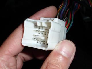
The bent pin appeared to be a ground pin, touching the K-line signal, causing all communication to die. After fixing the connector, all communication was back and codes could be read again. It did however not solve the engine problems, it still ran badly and had no power.
The badly running engine
It appeared that the engine was running on only two cylinders. To find out why, a four channel automotive oscilloscope was connected to the injectors and the ignition. Both showed strange signals, but the injectors were focused on first.
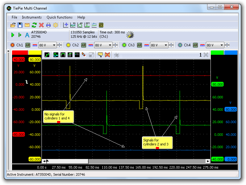
Figure 2 shows the injection signals of all four cylinders, but cylinders 1 and 4 show no injection pulses. After stopping and starting the engine again, new measurements could also show proper pulses for cylinders 1 and 4 and missing pulses for cylinder 2 and 3. Defective injectors or defective wiring cannot cause this, this had to be a problem at the control unit side.
It could also happen that when the throttle was increased, all injectors would operate normally, but the throttle plate would remain fully closed.
The ignition system also showed strange signals, see figure 3.
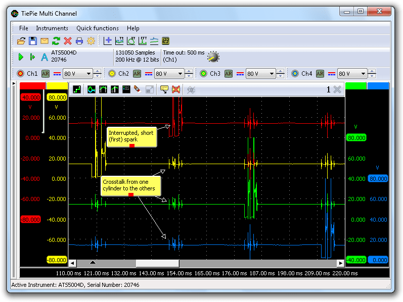
This could of course be intended operation, but in the spark signals of cylinder 1 occasionally a very short spark was seen. When checking the spark plug for cylinder 1, the center electrode appeared to be off-center. After replacing the spark plug, the spark was okay, but the engine kept running badly.
Throttle adjustment
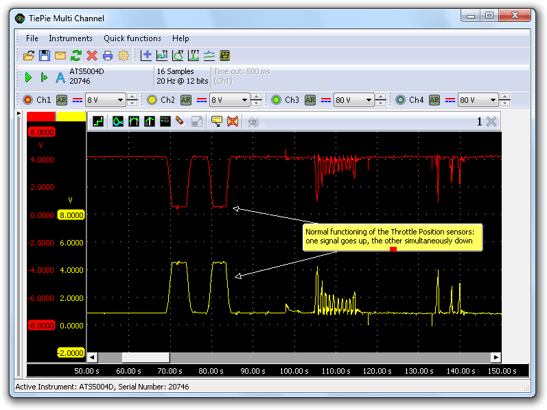
Since error codes regarding the electrically adjustable throttle kept reappearing, the throttle body was checked. It was noticed that the throttle plate did not move, indicated by the throttle position sensors (TPS) remaining on fixed values. After disconnecting the throttle and applying 12V to the electromotor that controls the plate, it appeared that the throttle valve did move and thus is functioning. At some moments however, both Throttle Position Sensor signals showed large fluctuations, while the engine kept running at the same speed, indicating that the throttle plate did not move. This could be a problem with the Throttle Position Sensors.
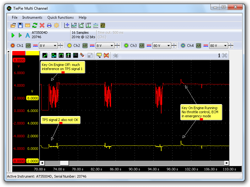
Figure 4 shows the two Throttle Position Sensor signals intermittently going to 0V. This could indicate a +5V power problem, therefore the 5V supply line of the ECM to the sensors was monitored. The 5V power remained stable during the intermittent fluctuations, ruling out the power supply for the sensors. Since the throttle body was already replaced, the only remaining plausible cause would be a wiring problem.
Cause and solution
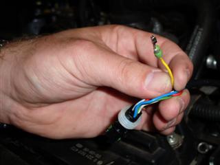
When thin back probes were inserted in the rear of the connector, to measure the sensor signals, the problem appeared to be gone and the engine was running properly, generating no more error codes. When the back probes were removed again, the problem reappeared. Examination of the connector showed that several terminals of the connector had insufficient contact pressure, resulting in a bad electrical connection.
The problems were solved by fixing the connector terminals. The two TPS signals behave normally, as seen in figure 6. Also ignition and injection patterns were normal again.
Conclusion
What has caused the low contact pressure in the connector terminals is not fully clear, perhaps a too thick test probe was inserted in the terminal to measure the signal, damaging the terminal. Thin back probes are available, which can be inserted in the back of connectors, between the terminal and the isolation, allowing to contact the terminals without causing any damage.
R. Metzelaar