Vehicle information
| Brand: | Renault |
| Model: | Kangoo |
| Year: | 1998 |
| Engine: | 1.4 |
| Engine code: | E7J 780 |
| Cylinder count: | 4 |
| Fuel type: | Petrol |
| Motor management system: | Siemens Fenix 5 |
Used equipment

Automotive Test Scope ATS5004D
4 channel automotive oscilloscope with differential inputs
Measure lead TP-C1812B
low noise differential BNC to banana measuring lead, 3 m
Back Probe TP-BP85
thin and flexible back probeThe Automotive Test Scope ATS5004D is in this article also referred to as automotive oscilloscope, as diagnosis oscilloscope and as lab scope.
Problem description
A 1998 Renault Kangoo was suffering from a bad start. The engine would start but then stall again. A fault code scanner showed no fault codes. A mechanic discovered that when one ignition coil group (this engine has DIS ignition) was disconnected, the engine would keep running, on two cylinders but at a too low rev count. The same happened when the other coil was disconnected. Using an automotive lab scope, many components were tested and all required signals appeared to be present. The car was examined by several garages and many items were "fixed": crankshaft sensor and connector replaced, fuel pump replaced, system relay replaced, injectors cleaned, spark plugs replaced and several mechanical adjustments performed. Even a Renault garage could not discover the problem: according to their test system the engine should run, but... it didn't. GMTO was then consulted and the car was brought in for examination.
Measuring
GMTO measured using a diagnosis oscilloscope and concluded that all relevant signals were present and seemed OK, the engine was supposed to run. One thing was noted: the charging time (or dwell angle) of the ignition coil control was unstable.
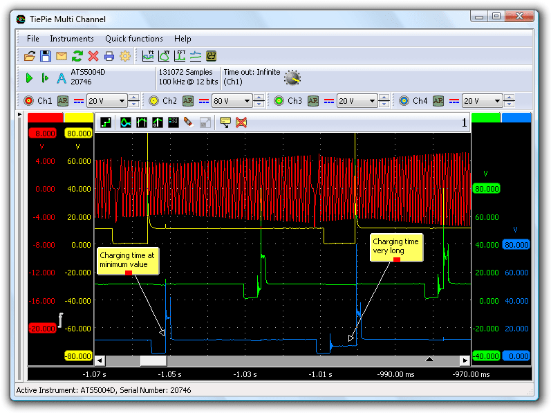
Figure 1 shows a charging time which varies strongly between two pulses, and also differs much from the other coil group. The current through the coils was then measured, but that showed no problems. The current would increase to 6 A and settle there. Current measurements in circuits like this are important, because they can show whether the coil contains enough energy to create a good spark. Figure 1 shows that the current regulation starts after 3.7 ms. The control module must then keep the charging time, the time that is required to let enough current flow through the coil to generate a proper spark, as short as possible to avoid the coil heating up. Ignition pulses with charging times more than two times larger than required were seen. Since there was enough spark energy available, this was not considered to cause the engine not to start.
Full start and stall cycle
Figure 2 shows the full start and stall cycle of the engine. This cycle only lasts 2 seconds.
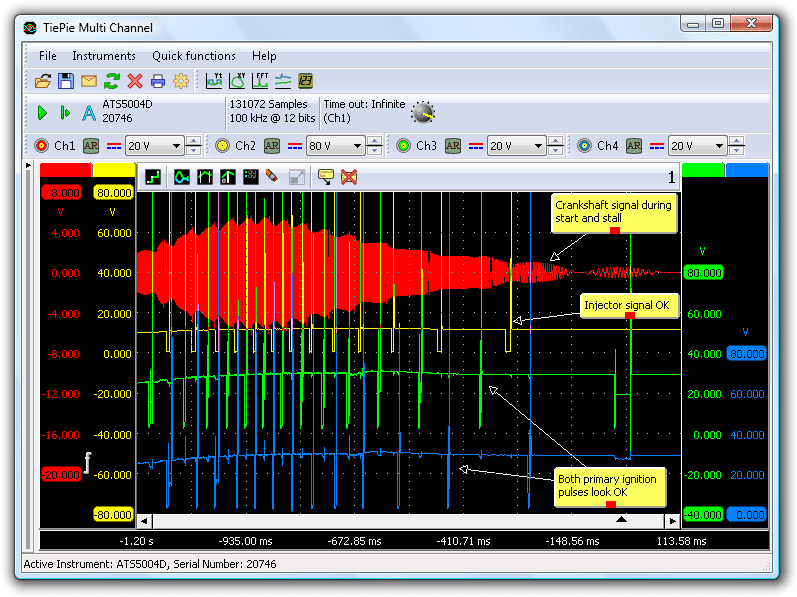
The upper signal, Ch1, shows the crankshaft signal, in which is clearly visible that the engine starts and then stops again. The image looks compressed, but it is measured with a long record and a high sampling rate, so zooming in still gives lots of detail. The second signal, Ch2, is an injector signal. This signal shows no strange things, it has a good opening time and the proper injection rate. The third and fourth signals are the two ignition coil groups. From start to end, sparks were generated.
Further measurements
Analysis of the signals measured with the automotive oscilloscope brought the following conclusion: there was either a mechanical problem or a timing problem in the ignition system. The latter happens only very rare.
Then the Top Dead Center (position of a piston in which is farthest from the crankshaft) moment in relation to the crankshaft signal was determined. This can be done by measuring the starting current or battery voltage and the crankshaft signal together. The highest current or lowest voltage indicates the TDC. TDC usually does not correspond with the reference point in the crankshaft signal. For this engine it turned out that TDC is 14 teeth after the missing tooth (reference point). Knowing this, it was possible to analyze the timing of the various signals.
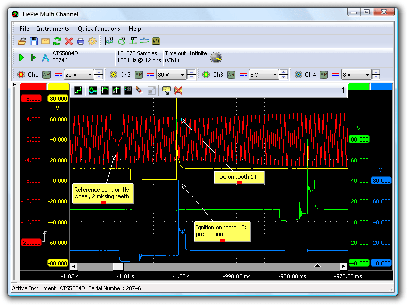
Figure 4 shows the signals at the moment the engine starts. The ignition peak corresponds with tooth 13. That is one tooth before TDC. The crankshaft signal contains 60 periods per revolution, so 1 tooth means 6 degrees of the crankshaft, corresponding with 6 degrees pre-ignition.
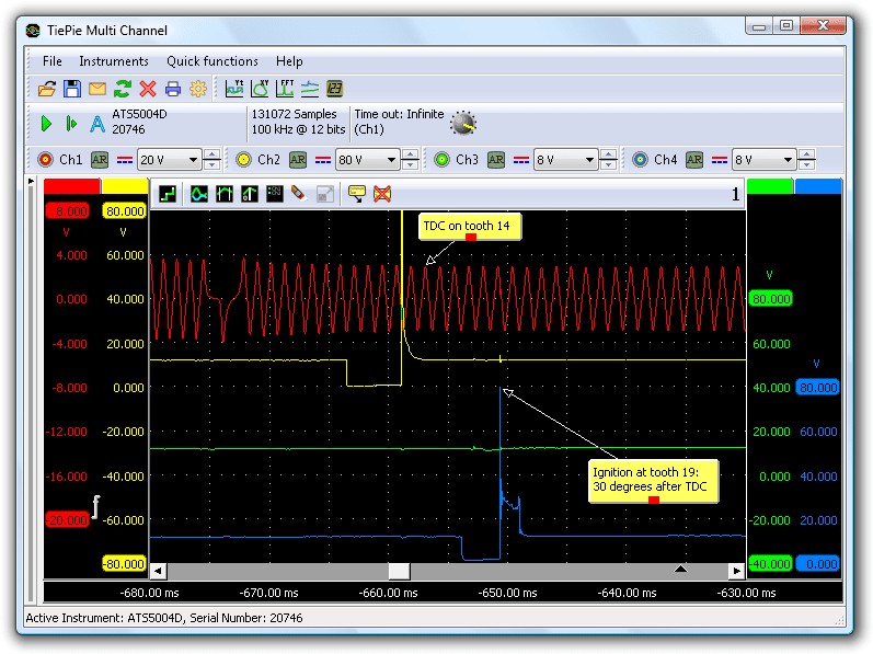
In figure 5 is zoomed in at the moment that the engine stops again. The ignition peak falls long after TDC, on tooth 19 to be exact. That means 19 - 14 = 5 teeth after TDC or 5 x 6 = 30 degrees after TDC! Much too late...
The cause
It is now clear that the late ignition causes the engine not to start. But what causes the ignition to become too late? Timing of a motor management system is controlled by software, based on signals from the crankshaft sensor and other sensors. Sensors that can affect the ignition timing are the Manifold Absolute Pressure (MAP) sensor, the knock sensor and the engine revolutions sensor. These sensors can however not cause the ignition become this late. The signals of these sensors were checked and found to be OK. Because fluctuations on the power of a control module can cause strange problems, the power and ground of the control module were checked during starting, but they turned out to be correct.
It seemed the only possible cause left was a defect in the control unit. This was discussed with the garage and the car was returned with the advice to replace the control module. After replacement, the garage reported that the problem was not solved. The car still showed the same symptoms.
Then it had to be the crankshaft sensor. In one of the initial attempts to fix the problem, the crankshaft sensor and its connector and some wiring were replaced. The new wiring had to be connected to the existing wiring. It was visible that this was done properly: pink to pink and yellow to yellow. We advised the garage to swap the two wires. They reported back that the car now starts well and runs fine.
When the crankshaft signal is connected in the wrong way, the signal will be inverted. The control unit will use the inverted signal and will draw the wrong conclusion on the exact position of the crankshaft, generating the required signals at the wrong moments.
Conclusion
We assume that the following happened: This car was brought to a garage with a no start condition. The garage then replaced the (truly defective) crankshaft sensor, connector and part of the wiring. The new connector had reversed wire colors and therefore was connected the wrong way around. The car would still not start, but the crankshaft sensor was not suspected, as it was just replaced. The fact that the signal patterns were now different was probably overlooked.
R. Metzelaar