Vehicle information
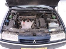
| Brand: | Citroën |
| Model: | Xantia |
| Year: | 1999 |
| Engine: | 2.0 L |
| Engine code: | XU10 J2C |
| Cylinder count: | 4 |
| Fuel type: | Petrol |
| Motor management system: | Magneti Marelli 8P |
Used equipment

Automotive Test Scope ATS5004D
4 channel automotive oscilloscope with differential inputs
Automotive Test Scope ATS5000
2 channel automotive oscilloscope with Arbitrary Waveform Generator
Measure lead TP-C1812B
low noise differential BNC to banana measuring lead, 3 m
Back Probe TP-BP85
thin and flexible back probe
The Automotive Test Scope ATS5004D is in this article also referred to as automotive oscilloscope, diagnosis oscilloscope and as lab scope.
Introduction
Diagnosing problems in cars requires knowledge of the systems in the car, but also requires the right tools. An oscilloscope is indispensable in many situations, but when an inappropriate oscilloscope is used, wrong conclusions can be drawn. Wrong conclusions lead to wrong "solutions", that do not fix the car, but cost time and money.
Problem description
This 1999 Citroën Xantia had a new starter motor fitted, after which it would not run anymore. While cranking it would fire briefly and then die. The car’s battery had been disconnected for the starter motor job. A scan tool was used to check for faults. A crankshaft sensor code was logged, that is shown on some older cars when the key is on with the crankshaft not turning. The code could not be reset, so was regarded as a hard fault.
The ignition and injection were checked with an inappropriate late model scope. It was seen that the ignition worked on both DIS coils and that injection stopped after a few beats. The crankshaft sensor signal was checked with that scope and found to be good. All appropriate steps, well done so far, but what next?
The crankshaft sensor was replaced, regardless of the good signal and later the ECM was replaced all with no positive results. The question was if the immobilizer could have reset itself by disconnecting the battery. The car was then towed to another garage that uses AECS Equipment as supplier of their instruments and has a subscription to the AECS Equipment helpdesk, which was called for assistance.
Measuring
Using a different scan tool, the crankshaft sensor code was reset. Using an , both coils of the DIS ignition and an injection signal were measured. The measured signals are shown in figure 1.
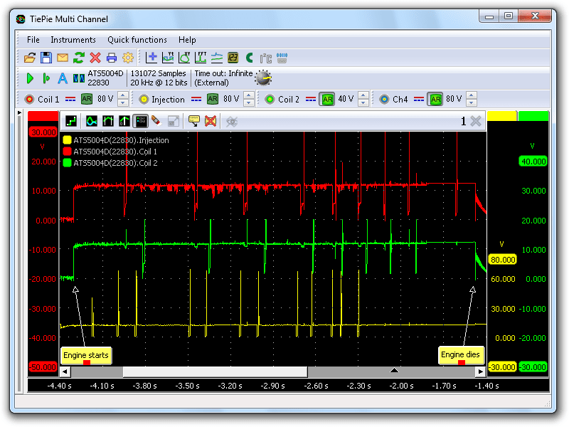
The engine briefly begins to run on 2 cylinders and dies again. For the trained eye it is visible that both ignition patterns are not 180 degrees offset. The irregular injection is normal during start enrichment. For better understanding what is happening, we add the crankshaft sensor signal to the recording.
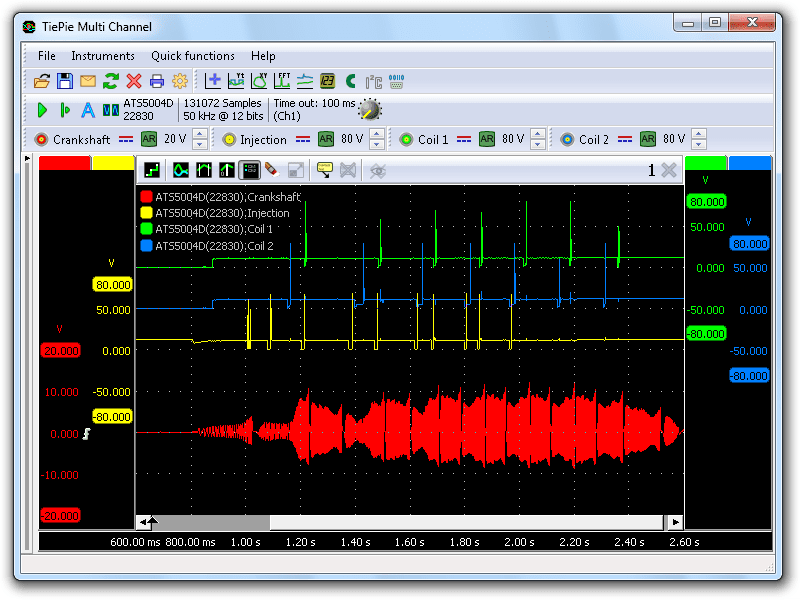
This is where things become clear. The wiring diagram (part of the ATIS software) shows that there are only 2 coils. That means we have 2 waste sparks. Each coil has to fire once per crankshaft revolution, causing a spark in two spark plugs, of which only one is causing combustion. Zooming in on the signals reveals what is happening.
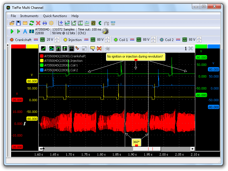
Figure 3 shows there is no ignition and no injection in every second revolution! This is why the engine ran on 2 cylinders when it briefly fired up. This is also why the first garage saw it firing on both coils and saw injection.
It is also obvious that the crankshaft pattern is present, so why the incorrect activation? The devil is always in the detail!
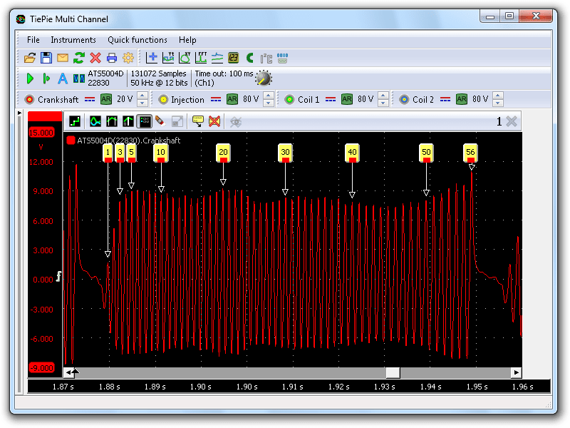
Figure 4 shows the crankshaft signal zoomed in to the selected revolution in figure 3. For clarity, the other signals were taken off the graph. The zoomed in pattern shows a healthy 56 teeth on the crankshaft tone wheel, although the number 1 tooth looks a bit low in voltage. Looking at the sample pattern in the ATIS software revealed that the Citroën Xantia needs to have 58 teeth!
Simulate
To verify that, an Automotive Test Scope ATS5000 was taken. This instrument has an Arbitrary Waveform Generator that can be used to output any signal. Through ATIS it was loaded with the 58 teeth pattern a Xantia needs to have. The crankshaft sensor was disconnected and the generator leads where connected to the crankshaft sensor connector. The fuel pump connector was disconnected as the injection could flood the engine. The 4 channel recording with the Automotive Test Scope ATS5004D is seen in figure 5.
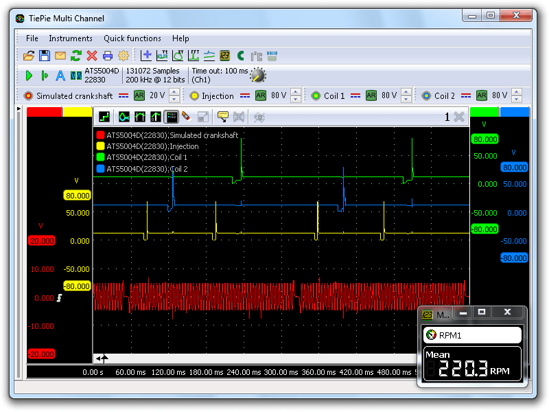
The generated proper pattern makes the ECM inject and ignite each revolution (360°) for as long as the signal generator runs.
Cause
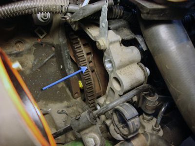
With the real crankshaft signal with 56 pulses, the engine would not run, with a simulated crankshaft signal with 58 pulses, the motor management system works fine. This proves that the system actually does require 58 pulses. A problem in the crankshaft sensor can not cause this repetitive loss of two pulses each revolution, this must have a mechanical cause. A close look at the crankshaft tone wheel revealed the actual problem.
Solution
The tone wheel was repaired after which the car ran fine again.
Conclusion
It was now clear what went wrong. While fitting the starter motor the starter housing must have hit the crankshaft tone wheel, knocking 2 teeth over. The ECM was waiting after every 58 teeth for the reference mark to pass the sensor again. This waiting was spent NOT injecting and NOT igniting.
The scope used by the first garage apparently did not reveal that ignition and injection only occurred every second revolution, nor that the crankshaft signal was missing pulses. With the Automotive Test Scope ATS5004D used by the second garage, long measurements with a high resolution can be taken. This not only gives a good overview during a longer time but also allows to zoom in on the smallest details in a signal.
Sending a pre-set crankshaft signal from ATIS with the Automotive Test Scope ATS5000 into the car’s wiring loom revealed a perfect ignition and injection pattern for as long as we wanted. So it was no ECM or immobilizer fault, just a crankshaft tone wheel which had a few teeth knocked by the starter motor replacement.
Only with proper automotive diagnostic instruments like the Automotive Test Scope ATS5004D and ATIS and a thorough training in automotive diagnostics, problems like this are easily solved.