Sensor information
| Type: | Zirconia oxygen sensor |
|---|---|
| Power supply: | 12 V from system relay |
| Signal type: | Signal: amplitude varying, heating: duty cycle varying |
| Signal level: | Signal 0.1 V to 0.8 V, heating: 0 V to 12 V |
Workings of the zirconia lambda sensor
With the lambda sensor or zirconia oxygen sensor the concentration difference in oxygen levels of two gases can be measured. The sensor consists of a plate zirconium dioxide (zirconia) to which a thin layer of platinum is applied at both sides. When an oxygen concentration difference exists between the two sides, a voltage difference will be present between the two platinum plates. The value of the voltage difference is in relation with the concentration difference. The sensor needs to be at an operating temperature of 300°C to perform well and therefore the sensor is usually equipped with an electronic heating element.
The lambda sensor is mounted on the exhaust pipe in such way that one side of the sensor is in contact with the exhaust gases and the other with the outside air. When a lean mixture is burnt, an amount of oxygen is left in the exhaust gases. This will create a small difference in oxygen levels compared with the outside air and the sensor produces a low signal voltage of approximately 0 to 0.1 V. When a rich mixture is burnt, the exhaust gases contain no oxygen and this will create a high concentration difference compared to the outside air which results in a voltage of approximately 0.8 V. The ideal mixture is when the signal voltage goes from 0.1 V to 0.8 V or back. At that moment the combustion is optimal and the exhaust gases contain a minimum amount of carbon monoxide. The lambda sensor is only able to detect if a mixture is too lean or rich.
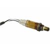
Zirconia oxygen sensor are available as several models which can be differentiated by the number of wires:
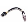
- 1 wire: non heated sensor with ground signal on the exhaust system
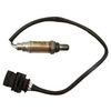
- 3 wires: heated sensor with signal ground on the exhaust system
- 4 wires: heated sensor with own signal ground wire, usually connected to ECU
The signal voltage of each model is equal. The heated sensors contain a PTC resistor for the heating to which the power is often supplied through the system relay. On most models the heating is not regulated and the ground wire of the heating element is connected directly to the ground via the ECU when the engine is running. When the heating is regulated, the ground wire is switched to the ground by the ECU with a varying duty cycle signal, also when the engine is running.
Connecting the lab scope
Correct functioning of the zirconia lambda sensor can be checked by measuring the following signal voltages, see figure 1:
| Channel | Probe | Voltage | Range |
|---|---|---|---|
| 1 |  |
Sensor output signal | 2 V |
 |
Ground at battery | ||
| 2 |  |
Signal from regulated heating | 20 V |
|
Ground at battery |
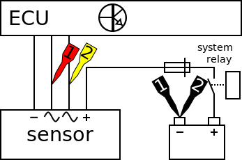
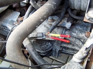
The lab scope is connected to the zirconia lambda sensor via a Measure lead TP-C1812B and Back Probe TP-BP85. The lab scope is set to recorder mode. In recorder mode a streaming measurement is performed, continuously displaying the signals live on screen. Because the measured signals vary slowly, the Automotive Test Scope ATS5004D is set to a slow measuring speed.
Measuring
Figure 3 shows waveforms of a zirconia lambda sensor and its regulated heater, measured at an idling engine at operating temperature. The signals can be downloaded and used to correctly set up the lab scope or as reference signal.
Download oxygen sensor measurement
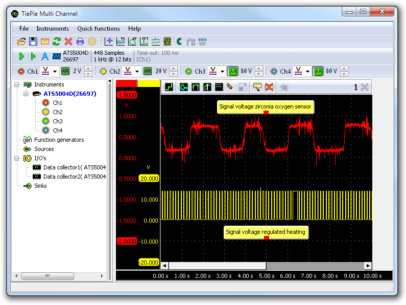
Channel 1 (red) shows the signal from the zirconia lambda sensor and channel 2 (yellow) the duty cycle signal for the regulated heating. The sensor signal is toggling between a low and high signal voltage. This proves that the engine management system is adapting the amount of injected fuel to approach the ideal mixture. The sensor signal contains some interference from the ignition and other components. This interference has no influence on the performance of the engine management system because the ECU has filtered inputs.
The yellow duty cycle signal is the regulated heating for the sensor. Other engine control units may not regulate the sensor heating. The heating will be permanently enabled in such cases and the heater signal should be in the range of 0 to 0.5 V.
A Duty Cycle I/O can be used to calculate the duty cycle percentage of the regulated heating signal.
Diagnosis
Signal values may differ on different types of engine control units and zirconia lambda sensor. Consult ATIS for information on specific engine control units and zirconia lambda sensor.
The following sensor signal deviations (channel 1) can indicate a problem:
-
No signal:
Cause: back probes have no connection (perform a connection test), no ground, sensor defective -
Signal voltage too high:
Cause: mixture is too rich (check with gas analyzer), sensor defective -
Signal voltage too low:
Cause: mixture is too lean (check with gas analyzer), leakage in exhaust system between engine and zirconia oxygen sensor, sensor defective -
Signal shows more noise than example signal:
Cause: wiring of ground or signal damaged, poor connection in connector terminals, sensor defective -
Signal shows an offset in relation of the example signal:
Cause: scope is not set to DC coupling: ,
sensor defective
,
sensor defective
The following heating signal deviations (channel 2) can indicate a problem:
-
No signal:
Cause: back probes have no connection (perform a connection test), amplifier of ECU defective, heating defective -
Signal voltage too high:
Cause: poor or no ground for ECU, resistance in wiring to ECU -
Signal voltage too low:
Cause: poor or no power supply -
Signal shows more noise than example signal:
Cause: wiring of signal damaged, poor connection in connector terminals -
Signal shows an offset in relation of the example signal:
Cause: scope is not set to DC coupling:,
poor or no ground for ECU, resistance in wiring to ECU
RELATED PRODUCTS


RELATED ARTICLES
- Broadband Oxygen Sensor
- With a lab scope a broadband oxygen sensor signal voltage is measured. The sensor signal is shown and can be downloaded. To help determining whether the broadband oxygen sensor is functioning correctly, different deviations from the example signal are mentioned along with possible causes.
- Toyota MR2 bad injector
- A Toyota MR2 is having problems after an engine replacement, fault code P0304 Cylinder #4 misfire detected occurs. The garage swaps several components but does not manage to fix the problem. Measurements with an automotive oscilloscope are required to find out that the fault code is somewhat misleading and the problem is not with cylinder #4
This document is subject to changes without notification. All rights reserved.
The information in this application note is carefully checked and is considered to be reliable, however TiePie engineering assumes no responsibility for any inaccuracies.
Safety warning:
- Before measuring, check that sources of dangerously high voltages are switched off or shielded from contact. Voltages considered to be dangerous are voltages over 30 V AC RMS, 42 V AC peak or 60 V DC.
- Keep a clean working environment when doing measurements.
- This measurement and procedures are a examples / measuring suggestions and are no prescribed protocols.
- TiePie engineering can not anticipate the safety actions that need to be taken to protect persons and appliances. Before starting a measurement, check which safety measures need to be applied.