Sensor information
| Type: | ABS sensor Hall effect |
|---|---|
| Power supply: | 12 V |
| Signal type: | frequency varying |
| Signal level: | Two wire: 6 mA to 17 mA, three wire: 0 V to 12 V |
Workings of a Hall effect ABS sensor
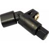
An anti lock braking system (ABS) sensor is used for determining wheel rotation speed to prevent wheel lock up when braking. The Hall effect ABS sensor consists of a permanent magnet with a Hall effect sensor next to it. The magnetic field strength changes when a magnetism sensitive object passes through the magnetic field of the magnet. This changing of the magnetic field causes the output of the Hall effect sensor to change.
In most cases the object used to influence the magnetic field is a disk or ring with evenly distributed teeth, mounted on the driveshaft or in the bearing. When the wheel is rotating, the teeth are passing the sensor and the pattern in which they are placed is visible in the ABS sensor signal. Each period of the signal is a tooth passing the sensor. The frequency of the signal depends on the rotation speed of the wheel and the amount of teeth on the disk or ring.
Two different types of Hall effect ABS sensor are used in cars, with either 2 wires or 3 wires.
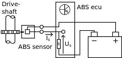
The 3 wire Hall effect ABS sensor has a simple power supply and a signal wire with the signal voltage (Us) going to the ABS ECU, shown in figure 1. Depending on the sensor design, the presence of a tooth causes either a high or a low signal voltage and a gap between teeth the opposite. The resulting signal is a square wave.
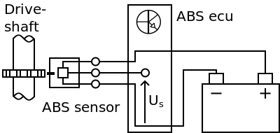
The 2 wire Hall effect ABS sensor has a 12 V power supply wire but no direct ground. As shown in figure 2 the ground of the sensor is also the signal wire. The 2 wire Hall effect ABS sensor is current regulating. The amount of current (Is) is changed by the sensor when a tooth is passing the sensor. Depending on the sensor design, the presence of a tooth causes either a high or a low current and a gap between teeth the opposite. This current flowing through the resistor inside the ABS ECU will produce a voltage (Us) related to the ground, similar to the square wave signal of the 3 wire Hall effect ABS sensor. The voltage levels are different and much lower than a 3 wire Hall effect ABS sensor because of the low currents. Voltage levels can also change from system to system depending on current flow and resistor values but a clear square wave pattern should be visible.
Connecting the lab scope
In this article the 2 wire Hall effect ABS sensor is measured. Instructions are shown on how to measure a 3 wire Hall effect ABS sensor so the 3 wire Hall effect ABS sensor can be measured as well. Signal patterns and diagnostic information for the 3 wire Hall effect ABS sensor can be read on the Hall effect crankshaft sensor page because they are similar.
Connecting to a 2 wire Hall effect ABS sensor
Correct functioning of the 2 wire Hall effect ABS sensor can be checked by measuring the following signal voltages, see figure 3:
| Channel | Probe | Voltage | Range |
|---|---|---|---|
| 1 |  |
Sensor output signal | 2 V |
 |
Ground at battery | ||
| 2 |  |
Positive side of sensor power supply | 20 V |
|
Ground at battery |
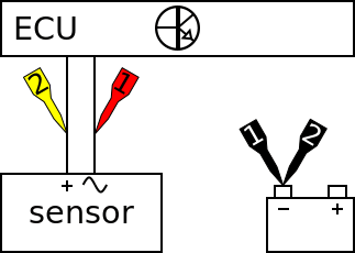
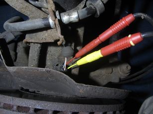
The lab scope is connected to the 2 wire Hall effect ABS sensor via a Measure lead TP-C1812B and Back Probe TP-BP85. The lab scope is set to normal scope mode with the trigger-timeout at infinite. When a one-shot measurement is started with these settings, the measurement is performed when the wheel is turned (by hand).
Connecting to a 3 wire Hall effect ABS sensor
Correct functioning of the 3 wire Hall effect ABS sensor can be checked by measuring the following signal voltages, see figure 5:
| Channel | Probe | Voltage | Range |
|---|---|---|---|
| 1 | |
Sensor output signal | 20 V |
|
Ground on battery | ||
| 2 | |
Positive side of sensor power supply | 20 V |
|
Negative side of sensor power supply |
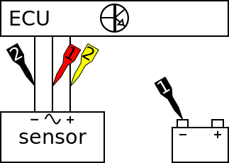
The lab scope is connected to the 3 wire Hall effect ABS sensor via a Measure lead TP-C1812B and Back Probe TP-BP85. The lab scope is set to normal scope mode with the trigger-timeout at infinite. When a one-shot measurement is started with these settings, the measurement is performed when the wheel is turned (by hand).
Measuring
Figure 6 shows a waveform of a 2 wire Hall effect ABS sensor with the wheel turned by hand with the ignition key turned to on. This signal can be downloaded and used to correctly set up the lab scope or as reference signal.
Download Hall effect ABS sensor measurement
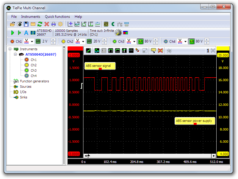
Channel 1 (red) shows the signal voltage of the Hall effect ABS sensor and channel 2 (yellow) the power supply. The signal starts with low frequency because the wheel rotates slowly. In the middle of the measurement the frequency is high due to higher speed of the rotation. At the end of the measurement the wheel is stopped again which can be seen in the dropping frequency of the signal. The power supply is slightly lower than 12 V which is partly down to the lower battery voltage but power supply levels are common lower on Hall effect ABS sensors. When zoomed in on the power supply signal it is possible to detect the square wave form of the output signal which is normal for this type of sensor.
When the Hall effect ABS sensor signals are measured while driving the vehicle the frequency will get higher while the amplitude remains the same. When the individual pulses in the signal become too narrow to be properly visible while driving, the sample frequency should be set higher with Increase/decrease sampling frequency.
Diagnosis
Signal values may differ on different types of engine control units and Hall effect ABS sensors. Consult ATIS for information on specific engine control units and Hall effect ABS sensors.
The following signal deviations can indicate a problem:
-
No signal:
Cause: back probes have no connection (perform a connection test), no power supply, poor or no connection between sensor and ECU, sensor defective -
Noisy signal:
Cause: poor power supply to Hall effect ABS sensor, poor connection in connector terminals, wiring of signal wire or power supply damaged -
Signal has faulty pattern:
Cause: tooth ring or disk damaged
RELATED PRODUCTS


RELATED ARTICLES
- ABS Sensor Inductive
- With a lab scope an inductive ABS sensor is measured on a wheel that is turned by hand. The signal from the sensor is shown and can be downloaded. To help determining whether an inductive ABS sensor is functioning correctly, different possible deviations from the example signal are mentioned along with possible causes.
This document is subject to changes without notification. All rights reserved.
The information in this application note is carefully checked and is considered to be reliable, however TiePie engineering assumes no responsibility for any inaccuracies.
Safety warning:
- Before measuring, check that sources of dangerously high voltages are switched off or shielded from contact. Voltages considered to be dangerous are voltages over 30 V AC RMS, 42 V AC peak or 60 V DC.
- Keep a clean working environment when doing measurements.
- This measurement and procedures are a examples / measuring suggestions and are no prescribed protocols.
- TiePie engineering can not anticipate the safety actions that need to be taken to protect persons and appliances. Before starting a measurement, check which safety measures need to be applied.