Vehicle information
| Brand: | Peugeot |
| Model: | 205 |
| Year: | 1994 |
| Engine: | 1.1 |
| Engine code: | HDZ |
| Cylinder count: | 4 |
| Fuel type: | Petrol |
| Motor management system: | G6 |
Used equipment

Automotive Test Scope ATS5004D
4 channel automotive oscilloscope with differential inputs
The Automotive Test Scope ATS5004D is in this article also referred to as automotive oscilloscope, as diagnosis oscilloscope and as lab scope.
Problem description
A Peugeot 205 from 1994, with G6 motor management system showed serious problems during acceleration. While accelerating, the engine would constantly hold back. The problem seemed worse during strong acceleration. The garage checked the fault code memory but found no codes. They even drove the car while monitoring the data stream from the Engine Control Module (ECM). During the holding back no strange things were found in the data stream. After replacing spark plugs and cables, DIS coil, camshaft sensor and throttle body, the car still showed the problem. GMTO was then contacted for assistance.
Measuring
The first things to measure with problems like this one, are the ignition and injection signals. These two systems are, what electronics is concerned, responsible for a good running engine.
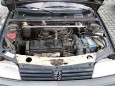
From ATIS, the Automotive Test and Information System of GMTO, which combines a large database with motor management system information with a sophisticated diagnosis oscilloscope, the snap shot mode was used. This setting allows to measure with the automotive oscilloscope during a longer time, triggered by a manual trigger button. When a problem arises while driving the car, a press on the trigger button will trigger the automotive oscilloscope. The total measurement can last several seconds and the lab scope will have captured a significant amount of data from before the trigger button was pressed. Due to the large memory of the diagnosis oscilloscope and the high sampling rate, a lot of detail is present, despite the long measurement time. The data is stored on the computer and can be examined later, back in the work shop.
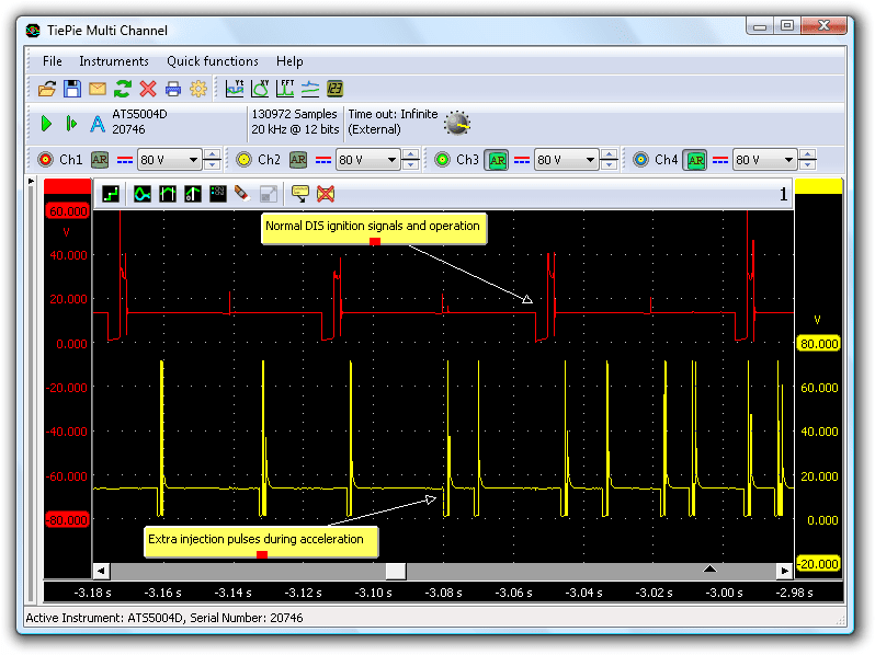
The measured data in figure 1 shows an unstable injector signal. It is common to inject some extra fuel in the first stage of an acceleration. This is usually done by the ECM by generating extra injection pulses and by increasing the opening time of the injectors. Besides the extra and longer injection pulses at the start of the acceleration, there were also injection pulses with a significant longer width in a later stage of the acceleration. Figure 2 shows an unexplained opening time difference of more than 1 millisecond between adjacent injection pulses, which indicates a problem.
The question was why in this stage of the acceleration extra and wider injection pulses appeared. Extra fuel in this stage results in the engine flooding and then holding back. What was measured here was a result of the problem, not the cause of the problem. The cause must be found somewhere else, probably in (one of) the sensors of the system.
Testing the sensors
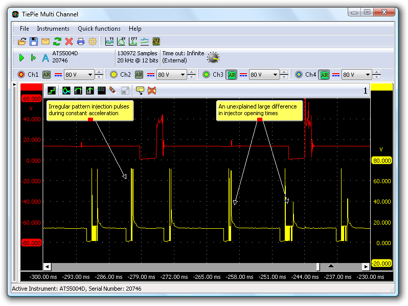
The next step in the diagnosis procedure is checking the relevant sensors. In this situation these are the Manifold Absolute Pressure (MAP) sensor and the throttle position sensor. These sensors inform the ECM about the acceleration situation and are therefore important to check during the occurrence of the problem. The diagnosis oscilloscope was connected to these sensors and set in the snap shot mode. At some point during driving the car the problem occurred and the manual trigger button was pressed to capture the sensor signals.
The MAP signal shows strange voltage drops with sharp edges. During the voltage drops, the throttle position signal does not change accordingly. We can therefore conclude that the pressure drops shown by the MAP sensor are not caused by sudden throttle position changes. The malfunction had to be found in the vacuum connection to the MAP sensor, the MAP sensor itself or in the wiring to the sensor.
MAP sensor
The MAP sensor signal in Figure 3 shows small fluctuations, which is normal. These are caused by the pressure variations in the input manifold. Each intake stroke, the pressure drops a little, which can be seen in the signal. Figure 3 also shows that at some points, the signal drops significantly to a much lower value. During 180 ms, the sensor output is suddenly 2.2 V lower. This is obviously not normal, but the fast rising slope after this sudden drop is what is really causing the problem. The ECM interprets this as a heavy acceleration and introduces extra and wider injection pulses. This causes flooding of the engine, resulting in holding back.
Solution
Why would the MAP signal drop so suddenly? The best strategy is not to immediately suspect the sensor, but first the electrical and mechanical components related to it. Only when these turn out OK, it is time to suspect the sensor.
After checking the vacuum system, nothing was found. Checking the sensor wiring resulted in finding the cause.
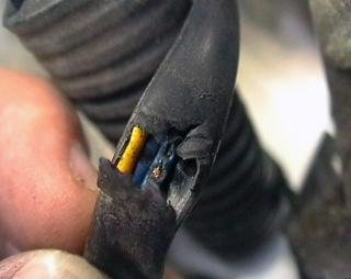
The isolation of the sensor wiring was damaged and one of the conductors was creating a short circuit to an engine support. This also explains why the problem only occurred during acceleration: the engine would slightly tilt and then cause the short circuit.
Conclusion
Older motor management systems are not always fast enough to detect problems. The fault situation was relative short (0.2 s) and therefore not recognized by the ECM. The fact that the signal dropped to 1.3 V and not to zero was not helpful either. Usually, a threshold of approximately 0.2 to 0.4 V is used to determine fault situations. Only when the signal comes below the threshold, the ECM will signal the fault situation. In that case, measuring with a diagnosis oscilloscope gives the solution.
R. Metzelaar