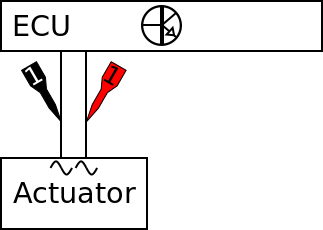
Actuator information
| Type: | DC motor |
|---|---|
| Power supply: | - |
| Signal type: | Duty cycle varying, positive or negative |
| Signal level: | -12 V to +12 V |
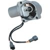
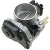
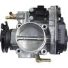
Workings of the throttle valve control motor
Lots of engine management systems contain an idle speed control motor. In older versions the idle speed is controlled with an external valve which bypasses the throttle valve. As a replacement for the external version, a throttle valve controlling the main throttle valve is used more and more. It is possible that the throttle valve control motor is used by a "drive by wire" system. The throttle valve control motor is then not only used for the idle speed regulation but also for an engine under (high) load.
The throttle valve control motor in this measurement example is a DC motor of which both terminals are connected to an H bridge in the ECU. The duty cycle and frequency of the H bridge signals vary. On other cars the signal might only be duty cycle varying.
A motor controlled throttle valve is kept in its neutral position by a spring. In this position the engine runs at a speed of about 1000 to 1500 RPM. When the engine needs to run at a lower speed, the ECU applies a positive duty cycle signal to the motor to nearly close the throttle valve. When the engine needs to run faster, a negative duty cycle signal is applied to further open the throttle valve. The polarity and duty cycle of the signal determines the direction and amount of opening of the throttle valve from its neutral position.
The ECU used the signal from the throttle valve position sensor to determine the exact position of the throttle valve.
Connecting the lab scope
Correct functioning of the control motor can be checked by measuring the following signal voltages, see figure 1:
| Channel | Probe | Voltage | Range |
|---|---|---|---|
| 1 |  |
Signal voltage at positive side of DC motor | 20 V |
 |
Signal voltage at negative side of DC motor |
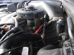
The lab scope is connected to the throttle valve control motor via a Measure lead TP-C1812B and Back Probe TP-BP85. The lab scope is set to normal scope mode with the trigger-timeout at infinite. When a one-shot measurement is started with these settings, the measurement is performed when the key is turned to the on position.
Measuring
Figure 3 shows a waveform of a throttle valve control motor with the key on and engine off. This signal can be downloaded and used to correctly set up the lab scope or as reference signal.
Download throttle valve position motor measurement
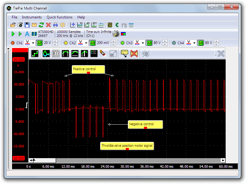
Channel 2 (red) shows the ECU generated control signal measured at the terminals of the throttle valve control motor. The measurement is started by turning the key to the on position. At the beginning of the measurement, the duty cycle signal is positive, followed by a short negative period. Subsequently the signal stays positive with a varying duty cycle signal to keep the throttle valve in a certain position to be able to let enough air pass when the engine would be started.
Diagnosis
Signal values may differ on different types of engine control units and throttle valve control motors. Consult ATIS for information on specific engine control units and throttle valve control motors.
The following signal deviations can indicate a problem:
-
No signal:
Cause: back probes have no connection (perform a connection test), H bridge defective, throttle valve control motor defective -
Signal voltage too high:
Cause: poor or no ground for ECU, resistance in wiring to ECU -
Noisy signal:
Cause: wiring of signal damaged, poor connection in connector terminals, throttle valve control motor defective -
Signal shows an offset:
Cause: scope is not set to DC coupling:
RELATED PRODUCTS


RELATED ARTICLES
- Throttle valve Position Sensor Single
- With a lab scope a throttle valve position sensor is measured with the key turned on and no running engine. The signal from the sensor is shown and can be downloaded. To help determining whether a throttle valve position sensor is functioning correctly, different possible deviations from the example signal are mentioned along with probable causes.
- Throttle valve Position Sensor Dual
- With a lab scope a throttle valve position sensor is measured with the key turned on and engine off. The signal from the sensor is shown and can be downloaded. To help determining whether a throttle valve position sensor is functioning correctly, different possible deviations from the example signal are mentioned along with possible causes.
- Acceleration Pedal Sensor
- With a lab scope an acceleration pedal position sensor is measured with the key turned on and no running engine. The signal from the sensor is shown and can be downloaded. To help determining whether an acceleration pedal position sensor is functioning correctly, different possible deviations from the example signal are mentioned along with probable causes.
This document is subject to changes without notification. All rights reserved.
The information in this application note is carefully checked and is considered to be reliable, however TiePie engineering assumes no responsibility for any inaccuracies.
Safety warning:
- Before measuring, check that sources of dangerously high voltages are switched off or shielded from contact. Voltages considered to be dangerous are voltages over 30 V AC RMS, 42 V AC peak or 60 V DC.
- Keep a clean working environment when doing measurements.
- This measurement and procedures are a examples / measuring suggestions and are no prescribed protocols.
- TiePie engineering can not anticipate the safety actions that need to be taken to protect persons and appliances. Before starting a measurement, check which safety measures need to be applied.