Sensor information
| Type: | Dual potentiometer |
|---|---|
| Power supply: | 5 V and ground from ECU |
| Signal type: | Amplitude varying |
| Signal level: | 0.6 V to 4.5 V |
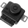
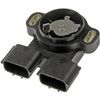
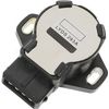
Workings of the throttle valve position sensor
The throttle valve position sensor contains a potentiometer or variable resistor that is used to provide the throttle valve position to the ECU. The sensor is constructed such that it can be mounted on the throttle valve body with the throttle shaft sticking into the sensor. This allows the slider of the potentiometer to move along with the throttle. Some throttle position sensors are equipped with two potentiometers to increase reliability.
In this measurement example a throttle valve position sensor is measured which contains two potentiometers. Its power is supplied by the ECU and is looped from the 1st to the 2nd potentiometer inside the sensor. Both potentiometers contain a carbon track which is connected to the power supply at one end and to ground at the other. The slider moving over the carbon track picks up the sensor voltage from which the ECU can determine the throttle valve position. Dual potentiometer throttle valve position sensor are available in two kinds: one uses two potentiometers with opposite signal, the other uses two potentiometers with a similar signal and offset between them.
Connecting the lab scope
Correct functioning of the throttle valve position sensor can be checked by measuring the following signal voltages, see figure 1:
| Channel | Probe | Voltage | Range |
|---|---|---|---|
| 1 |  |
Sensor output signal 1 | 8 V |
 |
Ground at battery | ||
| 2 |  |
Sensor output signal 2 | 8 V |
 |
Ground at battery | ||
| 3 |  |
Positive side of sensor power supply | 8 V |
|
Negative side of sensor power supply |
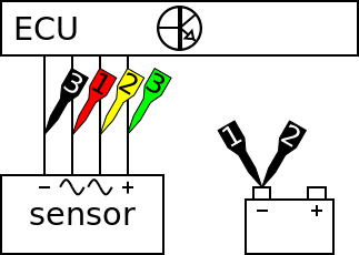
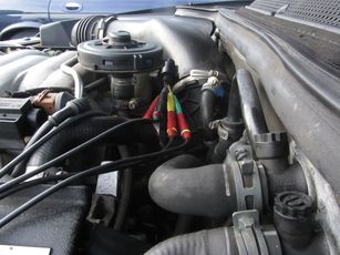
The lab scope is connected to the throttle valve position sensor via a Measure lead TP-C1812B and Back Probe TP-BP85. The lab scope is set to recorder mode. In recorder mode a streaming measurement is performed, continuously displaying the signals live on screen. Because the measured signals vary slowly, the Automotive Test Scope ATS5004D is set to a slow measuring speed.
Measuring
Figure 3 shows waveforms of a throttle valve position sensor with the key turned on and engine off. This signal can be downloaded and used to correctly set up the lab scope or as reference signal.
Download dual throttle valve position sensor measurement
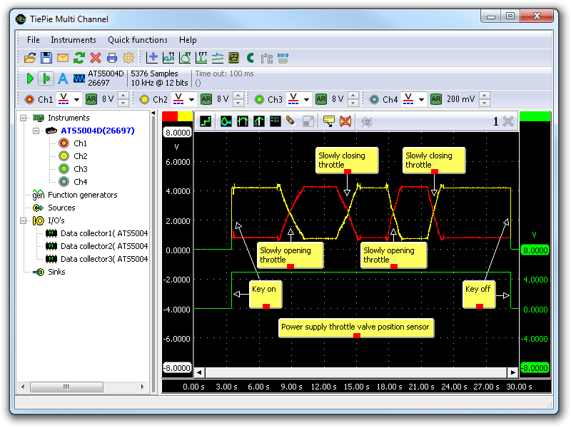
Channel 1 (red) shows the signal from the 1st potentiometer and channel 2 (yellow) the opposite signal from the 2nd potentiometer. Channel 3 (green) shows the power supply of both potentiometers. The throttle is slowly opened and closed twice during this measurement during which the complete range of the sensor is used. The signal voltage range is 0.6 V to 4.5 V, corresponding to the throttle valve fully closed and wide open respectively. On the 2nd potentiometer this is the other way around. The power supply constantly remains 5 V.
Diagnosis
Signal values may differ on different types of engine control units and throttle valve position sensors. Consult ATIS for information on specific engine control units and throttle valve position sensors.
The following signal deviations can indicate a problem:
-
No signal:
Cause: back probes have no connection (perform a connection test), no power supply, sensor defective -
Signal voltage too high:
Cause: poor or no ground on power supply, resistance in wiring to ECU, sensor defective -
Noisy signal:
Cause: wiring of signal or power supply damaged, poor connection in connector terminals, sensor defective -
Signal shows an offset in relation of the example signal:
Cause: scope is not set to DC coupling: ,
poor or no ground on power supply, resistance in wiring to ECU
,
poor or no ground on power supply, resistance in wiring to ECU
RELATED PRODUCTS


RELATED ARTICLES
- Throttle valve Position Sensor Single
- With a lab scope a throttle valve position sensor is measured with the key turned on and no running engine. The signal from the sensor is shown and can be downloaded. To help determining whether a throttle valve position sensor is functioning correctly, different possible deviations from the example signal are mentioned along with probable causes.
- Acceleration Pedal Sensor
- With a lab scope an acceleration pedal position sensor is measured with the key turned on and no running engine. The signal from the sensor is shown and can be downloaded. To help determining whether an acceleration pedal position sensor is functioning correctly, different possible deviations from the example signal are mentioned along with probable causes.
- Opel Agila with electrical problems
- An Opel Agila runs bad and generates lots of throttle related error codes. The garage replaces the throttle body, throttle position sensors, the ECM and even a part of the wiring harness, to no avail. When measuring the vital signals with an automotive oscilloscope, the cause of the problems is revealed.
This document is subject to changes without notification. All rights reserved.
The information in this application note is carefully checked and is considered to be reliable, however TiePie engineering assumes no responsibility for any inaccuracies.
Safety warning:
- Before measuring, check that sources of dangerously high voltages are switched off or shielded from contact. Voltages considered to be dangerous are voltages over 30 V AC RMS, 42 V AC peak or 60 V DC.
- Keep a clean working environment when doing measurements.
- This measurement and procedures are a examples / measuring suggestions and are no prescribed protocols.
- TiePie engineering can not anticipate the safety actions that need to be taken to protect persons and appliances. Before starting a measurement, check which safety measures need to be applied.