Actuator information
| Type: | Electronically activated valve |
|---|---|
| Power supply: | 12 V from system relay |
| Signal type: | Frequency and duty cycle varying |
| Signal level: | 0 V to 12 V and 60 V peak |
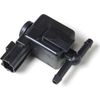
Workings of a canister purge valve
To prevent over pressure and under pressure in the fuel tank, it has to be vented to equalize the pressure. Because of environmental legislation the vented air must be filtered. When a car is sitting stationary and the temperature increases, the pressure in the fuel tank increases. The excess fumes are then vented through an active carbon filter that captures the fuel vapors. To prevent the filter from saturating, during driving air is sucked into the inlet manifold through the canister purge valve or regeneration valve, removing the vapors from the filter. This valve is electronically controlled by the ECU. When the valve is open, more fuel enters the cylinders. The ECU can detect this with the use of a lambda sensor and will compensate by adjusting the injector opening time.
The valve is normally held shut by a spring and is equipped with a coil. When a current flows through this coil, the resulting magnetic force opens the valve. The power to the canister purge valve is supplied from a system relay on the positive side. To activate the valve, the negative side is switched to ground by the ECU.
Connecting the lab scope
Correct functioning of the canister purge valve can be checked by measuring the following signal voltages, see figure 1:
| Channel | Probe | Voltage | Range |
|---|---|---|---|
| 1 |  |
Signal voltage at negative side of canister purge valve | 80 V |
 |
Ground at battery | ||
| 2 |  |
Power supply at canister purge valve | 20 V |
|
Ground at battery |
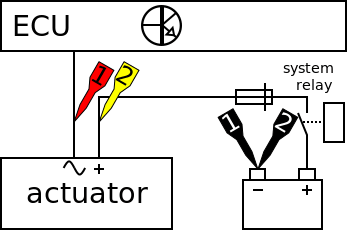
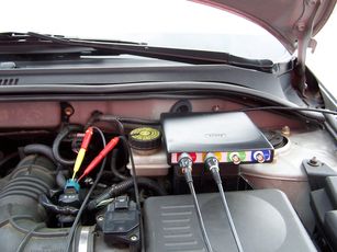
The lab scope is connected to the canister purge valve via a Measure lead TP-C1812B and Back Probe TP-BP85 and is set to normal scope mode.
Measuring
Figure 3 shows a waveform of a canister purge valve on an idling engine at operating temperature. This signal can be downloaded and used to correctly set up the lab scope or as reference signal.
Download canister purge valve measurement
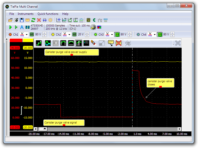
Channel 1 (red) shows the signal of the negative side of the canister purge valve, which is switched to ground by the ECU. At the beginning of the measurement the valve is not activated, no current is flowing and the signal has the same value as the battery voltage. When valve is activated by the ECU, the signal voltage drops to zero and a current starts flowing. The current builds up a magnetic field which opens the valve when strong enough to overcome the spring pressure.
When the valve has opened for long enough, the circuit in interrupted by the ECU at t = 0. Because the circuit is interrupted, the current stops immediately and the built up magnetic field starts to decay. The sudden change in current causes a high induction voltage. In this measurement the induction voltage is clipped by a diode to 48 V. When the magnetic becomes too weak to overcome the spring force, the valve is pushed back on its seat. The movement of the valve creates a change in the magnetic field, which is visible as a small hump in the signal.
The power supply of the canister purge valve is measured with channel 2 (yellow) and is equal to the battery voltage throughout the measurement. During the activation of the valve a current flows through it which can cause a little voltage drop.
The timing of canister purge valve opening and closing is not critical for correct engine operation.
Diagnosis
Signal values may differ on different types of engine control units and canister purge valves. Consult ATIS for information on specific engine control units and canister purge valves.
The following signal deviations can indicate a problem:
-
No signal:
Cause: back probes have no connection (perform a connection test), no power supply, ECU amplifier defective, canister purge valve defective -
Signal voltage to high (with activated valve):
Cause: poor or no ground for ECU, resistance in wiring to ECU -
Noisy signal:
Cause: wires of power supply or signal damaged, poor connection in connector terminals, canister purge valve defective -
Signal shows an offset:
Cause: poor or no ground for the ECU, resistance in wiring to ECU, scope is not set to DC coupling:
RELATED PRODUCTS


RELATED ARTICLES
- Indirect injection voltage measurement
- A lab scope is used to measure an injector signal voltage on an idling engine at operating temperature. The signal from the sensor is shown and can be downloaded. To help determining whether the injector is functioning correctly, different possible deviations from the example signal are mentioned along with possible causes.
- Oxygen sensor zirconia
- With a lab scope a zirconia lambda sensor is measured on an idling engine at operating temperature. The signal from the sensor is shown and can be downloaded. To help determining whether a zirconia lambda sensor and its heating is functioning correctly, different possible deviations from the example signals are mentioned along with probable causes.
This document is subject to changes without notification. All rights reserved.
The information in this application note is carefully checked and is considered to be reliable, however TiePie engineering assumes no responsibility for any inaccuracies.
Safety warning:
- Before measuring, check that sources of dangerously high voltages are switched off or shielded from contact. Voltages considered to be dangerous are voltages over 30 V AC RMS, 42 V AC peak or 60 V DC.
- Keep a clean working environment when doing measurements.
- This measurement and procedures are a examples / measuring suggestions and are no prescribed protocols.
- TiePie engineering can not anticipate the safety actions that need to be taken to protect persons and appliances. Before starting a measurement, check which safety measures need to be applied.