Sensor and actuator information
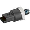
| Sensor type: | Fuel pressure sensor |
|---|---|
| Power supply: | 5 V and GND from ECU |
| Signal type: | Amplitude varying |
| Signal level: | 0,5 V to 4,5 V |
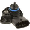
| Actuator type: | Fuel metering valve |
|---|---|
| Power supply: | 12 V from system relay |
| Signal type: | Duty cycle varying, ground switched |
| Signal level: | 0 V to 12 V, battery voltage |
Workings of the fuel pressure sensor and metering valve
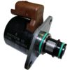
Fuel delivery systems on modern engines use an adjustable fuel pressure, where the pressure is adapted to accommodate the required power output of the engine. The combination of fuel pressure and injector opening time determine the amount of injected fuel in the cylinder. This kind of adaptive fuel pressure control consists of a mechanical high pressure fuel pump with fuel metering valve, see figure 1, and a fuel rail with fuel pressure sensor. The high fuel pressures used in these systems also improve fuel atomization at the injector nozzle.
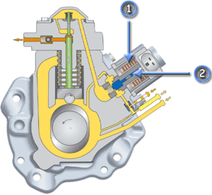
- Solenoid
- Plunger
To adapt the fuel pressure in the rail, the fuel metering valve on the mechanical fuel pump controls the amount of fuel entering the pump. The plunger is held fully open by a spring to let fuel pass through. To reduce the amount of fuel, the opening is reduced by moving the plunger against the spring's pressure, using a magnetic field generated by powering the solenoid. The plunger's position is controlled by the ECU, based on the required engine output and the current fuel pressure measured by the fuel pressure sensor.
The fuel metering valve solenoid is powered from a system relay on the positive side and the ECU switches the negative side to the ground. The duty cycle of the signal determines the position of the plunger, increasing the duty cycle will increase the fuel pressure, decreasing the the duty cycle decreases the fuel pressure. The fuel pressure sensor signal indicates the pressure in the fuel rail, the signal voltage increases as the fuel pressure increases.
Connecting the lab scope
Correct functioning of the fuel pressure sensor and fuel metering valve can be checked by measuring the following signal voltages, see figure 2:
| Channel | Probe | Voltage | Range |
|---|---|---|---|
| 1 |  |
Fuel pressure sensor signal voltage | 8 V |
 |
Ground at battery | ||
| 2 |  |
Fuel metering valve signal voltage | 20 V |
 |
Ground at battery |
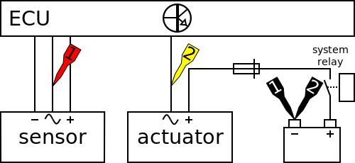
The lab scope is connected to the fuel pressure sensor and fuel metering valve both via a Measure lead TP-C1812B and Back Probe TP-BP85 and is set to recorder mode.
In recorder mode a streaming measurement is performed, continuously displaying the signals live on screen. Because the measured signals vary slowly, the Automotive Test Scope ATS5004D is set to a slow measuring speed.
Measuring
Figure 4 shows a waveform of the fuel pressure sensor and metering valve measured at the following conditions: key on, starting engine, 2000 RPM and 3000 RPM, with an engine at operating temperature. This signal can be downloaded and used to correctly set up the lab scope or as reference signal.
Download fuel pressure and fuel metering valve measurement
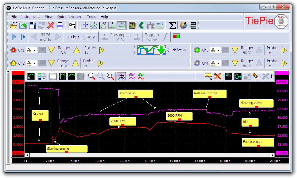
Channel 1 (red) in figure 4 shows the fuel pressure sensor signal. The duty cycle signal from channel 2 is converted to a duty cycle percentage by a duty cycle I/O and placed in the graph, purple signal. When the key is switched on the fuel pressure sensor shows a low voltage, meaning there is little or no fuel pressure. This low fuel pressure causes the ECU to drive the fuel metering valve with a high duty cycle signal. Once the engine is running the mechanical fuel pump starts to work, which increases the fuel pressure. When the required fuel pressure for idle running is reached, the duty cycle decreases and stabilizes to a value causing a fuel pressure required to maintain the engine running. During the measurement the throttle is pushed twice to reach 2000 and 3000 RPM after which it is released again. The increase in the duty cycle signal is followed by the increase in fuel pressure that is needed to keep the engine running at the increased engine speeds.
Diagnosis
Signal values may differ on different types of engine control units, fuel pressure sensors and metering valves. Consult ATIS for information on specific engine control units, fuel pressure sensors and metering valves.
The following fuel pressure sensor signal (channel 1) deviations can indicate a problem:
-
No signal:
Cause: back probes have no connection (perform a connection test), no power supply, sensor defective -
Signal voltage too high or too low:
Cause: scope is not set to DC coupling: , poor or no power supply, sensor defective
-
Signal shows more noise than example signal:
Cause: signal wires damaged, poor connection in connector terminals, sensor defective -
Signal shows an offset in relation to the example signal:
Cause: scope is not set to DC coupling:,
poor connection in connector terminals, sensor defective
The following fuel metering valve signal (purple duty cycle level) deviations can indicate a problem:
-
No signal:
Cause: back probes have no connection (perform a connection test), no power supply, actuator defective -
Signal voltage too low:
Cause: signal wires damaged, poor connection in connector terminals, actuator defective -
Signal shows an offset in relation to the example signal:
Cause: scope is not set to DC coupling:,
actuator defective
RELATED PRODUCTS


RELATED ARTICLES
- Direct injection servo hydraulic voltage and current measurement
- Lab scope measurement of servo hydraulic injector voltage and current on an idling engine at operating temperature. The measured voltage and current is shown and can be downloaded. To help determining whether the servo hydraulic injector is functioning correctly, different possible deviations from the example signal are mentioned along with possible causes.
This document is subject to changes without notification. All rights reserved.
The information in this application note is carefully checked and is considered to be reliable, however TiePie engineering assumes no responsibility for any inaccuracies.
Safety warning:
- Before measuring, check that sources of dangerously high voltages are switched off or shielded from contact. Voltages considered to be dangerous are voltages over 30 V AC RMS, 42 V AC peak or 60 V DC.
- Keep a clean working environment when doing measurements.
- This measurement and procedures are a examples / measuring suggestions and are no prescribed protocols.
- TiePie engineering can not anticipate the safety actions that need to be taken to protect persons and appliances. Before starting a measurement, check which safety measures need to be applied.