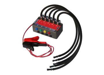
Diesel Return Flow Sensor RFS400 information
| Type: | Diesel Return Flow Sensor RFS400 |
|---|---|
| Power supply: | 12 V from battery |
| Signal type: | Amplitude varying |
| Signal level: | - |
Workings of the Diesel Return Flow Sensor RFS400
In a common rail diesel engine, a high pressure fuel pump supplies diesel fuel to all injectors. When fuel inside a cylinder is required, the motor management system will open the injector of that cylinder to inject the required amount of fuel in the cylinder. Opening the injector uses a hydraulic mechanism, which uses part of the available fuel as hydraulic fluid. This fuel then flows back to the fuel tank. When an injector is defective and will not open properly, less fuel is used by the hydraulic mechanism, resulting in less return flow. When the injector will not close properly, more fuel is used by the hydraulic mechanism, resulting in more return flow.
To check the state of the injectors, the return flow of the individual injectors can be measured and compared to the return flow of the other injectors. A common method is to disconnect the return lines and capture the returned fuel in little jars, one for each injector. After running the engine for a while, the amount of fuel in the jars is measured and compared and a defective injector can be spotted. This method has a few drawbacks. It cannot be used in fuel injection systems where the return lines are pressurized. Secondly is it complicated to perform this test in a driving car, in situations where the problem only occurs while driving. And there is the risk of spilling fuel, due to the open jars.
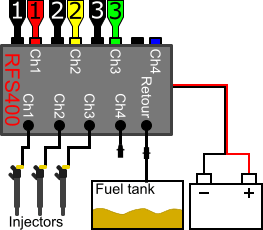
The Diesel Return Flow Sensor RFS400 solves all these problems. It measures the return flow of the injectors in a closed system which can be pressurized. The Diesel Return Flow Sensor RFS400 is placed between the return flow connections of the injectors and the fuel tank so no fuel is spilled. Due to the closed system, it is also possible to perform the test in a driving car. When connected to an automotive lab scope, the return flow is presented in clear graphs, indicating how the injectors are functioning.
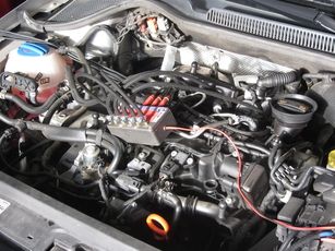
This particular measurement is performed on the same engine as the servo hydraulic injector measurement.
Connecting the Diesel Return Flow Sensor RFS400 and the lab scope
The Diesel Return Flow Sensor RFS400 has four channels, of which only three are used in this measurement. For connecting the Diesel Return Flow Sensor RFS400 and the lab scope, see figure 1:
| Channel | Probe | Voltage | Range |
|---|---|---|---|
| 1 |  |
Diesel Return Flow Sensor RFS400 channel 1 positive connection | 4 V |
 |
Diesel Return Flow Sensor RFS400 channel 1 negative connection | ||
| 2 |  |
Diesel Return Flow Sensor RFS400 channel 2 positive connection | 4 V |
|
Diesel Return Flow Sensor RFS400 channel 2 negative connection | ||
| 3 |  |
Diesel Return Flow Sensor RFS400 channel 3 positive connection | 4 V |
|
Diesel Return Flow Sensor RFS400 channel 3 negative connection |
In recorder mode a streaming measurement is performed, continuously displaying the signals live on screen. Because the measured signals vary slowly, the Automotive Test Scope ATS5004D is set to a slow measuring speed.
Measuring
Figure 3 shows a waveform of the return flow from the injectors of a car with revved engine. This signal can be downloaded and used to correctly set up the lab scope or as reference signal.
Download RFS400 diesel return flow measurement
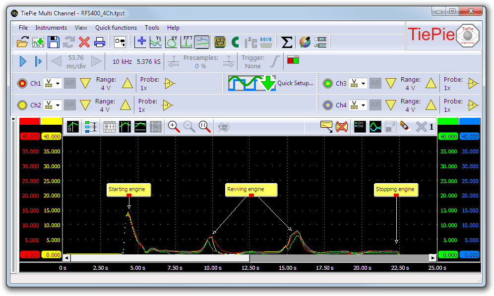
In figure 3, channel 1 (red) shows the return flow of injector 1, channel 2 (yellow) shows the return flow of injector 2 and channel 3 (green) shows the return flow of injector 3. In this measurement the engine is started, after which it is left to stabilize to idle speed. Subsequently the engine is revved twice to induce a larger return flow, and finally the engine is stopped again. In this measurement it is allowed to have some differences between injector return flows but any major deviation between the individual signals can indicate faulty injectors.
Diagnosis
Signal values may differ on different types of engine control units and injectors. Consult ATIS for information on specific engine control units and injectors.
The following signal deviations can indicate a problem:
-
No signal:
Cause: probes have no connection (perform a connection test), no power supply to the Diesel Return Flow Sensor RFS400, incorrect return line connections -
Signal voltage too high:
Cause: possible defective injector -
Signal voltage too low:
Cause: possible defective injector
RELATED PRODUCTS


RELATED ARTICLES
- Direct injection servo hydraulic voltage and current measurement
- Lab scope measurement of servo hydraulic injector voltage and current on an idling engine at operating temperature. The measured voltage and current is shown and can be downloaded. To help determining whether the servo hydraulic injector is functioning correctly, different possible deviations from the example signal are mentioned along with possible causes.
This document is subject to changes without notification. All rights reserved.
The information in this application note is carefully checked and is considered to be reliable, however TiePie engineering assumes no responsibility for any inaccuracies.
Safety warning:
- Before measuring, check that sources of dangerously high voltages are switched off or shielded from contact. Voltages considered to be dangerous are voltages over 30 V AC RMS, 42 V AC peak or 60 V DC.
- Keep a clean working environment when doing measurements.
- This measurement and procedures are a examples / measuring suggestions and are no prescribed protocols.
- TiePie engineering can not anticipate the safety actions that need to be taken to protect persons and appliances. Before starting a measurement, check which safety measures need to be applied.