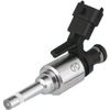
Actuator information
| Type: | Direct injection, coil operated |
|---|---|
| Power supply: | - |
| Signal type: | Frequency varying |
| Signal level: | -70 V to +70 V |
Workings of a direct injector
Direct petrol injection is becoming more common on internal combustion engines and replaces the indirect petrol injection to enhance engine performance and lower fuel consumption. A direct petrol injector injects the fuel directly into the combustion chamber. The injection of fuel can be done during the induction stroke for a homogeneous injection or during the compression stroke for a stratified injection.
The direct injector electrically works just like the indirect injector. The difference with the indirect injector is that the direct injector contains a low resistance coil of which both ends are connected to the ECU. The ECU contains adapted circuits to control the direct injector in such way that the opening and closing times are shortened as much as possible.
Connecting the lab scope
Correct functioning of the direct injector can be checked by measuring the following signal voltages, see figure 1:
| Channel | Probe | Voltage | Range |
|---|---|---|---|
| 1 |  |
Injector voltage positive side | 80 V |
 |
Injector voltage negative side | ||
| 2 |  |
Current clamp positive connection | 2 V |
|
Current clamp negative connection |
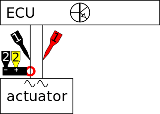
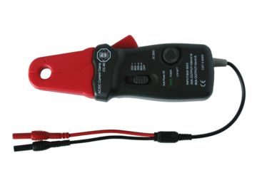
Channel 1 of the lab scope is connected to the direct injector via a Measure lead TP-C1812B and Back Probe TP-BP85. The current is measured with a Current clamp TP-CC80 which is connected to channel 2 of the lab scope with the use of a Measure lead TP-C1812B. The Current clamp TP-CC80 is set to the 20 ADC range and outputs a voltage of 100 mV per 1 A. To get a readout in Ampères, the current clamp's signal voltage has to be amplified 10 times. This can be done via the menu item "probe settings" in the right click menu of channel 2. In that same menu the "Set unit..." can be used to change the unit to 'A'. The lab scope is set to normal scope mode.
Measuring
Figure 3 shows a waveform of the direct injector of a car with idling engine at operating temperature. This signal can be downloaded and used to correctly set up the lab scope or as reference signal.
Download direct petrol injection measurement
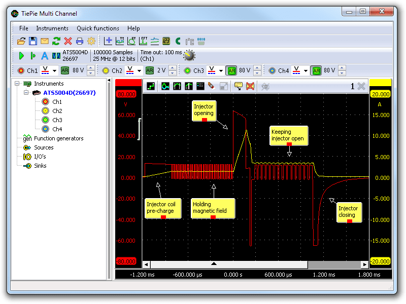
In figure 3 channel 1 (red) shows the signal voltage and channel 2 (yellow) the current signal of the direct petrol injector.
Let's concentrate on the signal voltage (red). Starting form the left, the ECU applies a voltage to charge the coil with a magnetic field and shortly after applies a duty cycle signal to hold the magnetic field. This is done to minimize the time needed for opening the injector. When an injection is needed, the ECU applies a relative high voltage to open the injector as quickly as possible, after which it applies a short negative voltage to reduce the current through the coil.
After this, the coil stays powered with a duty cycle signal that is now present on the coil as can be seen in the current signal, which is higher and indicates the injector is still being held open. The current and magnetic field are kept just large enough to keep the injector open, to minimize the time needed to close the injector. When the injector needs to be closed, the ECU applies a relative high negative voltage to close it as fast as possible.
Diagnosis
Signal values may differ on different types of engine control units and direct injectors. Consult ATIS for information on specific engine control units and direct injectors.
The following direct injector voltage (channel 1) deviations can indicate a problem:
-
No signal:
Cause: back probes have no connection (perform a connection test), direct injector defective -
Noisy signal:
Cause: signal wires damaged, poor connection in connector terminals, direct injector defective -
Signal voltage too low:
Cause: back probes have no connection (perform a connection test), resistance in wiring to ECU -
Signal shows an offset in relation to the example signal:
Cause: scope is not set to DC coupling:
The following direct injector current (channel 2) deviations can indicate a problem:
-
No signal:
Cause: current clamp not properly connected (perform a connection test), current clamp is not switched on or has a empty battery, direct injector defective -
Noisy signal:
Cause: signal wires damaged, poor connection in connector terminals, direct injector defective -
Signal shows an offset in relation to the example signal:
Cause: current clamp was not properly zeroed
RELATED PRODUCTS


RELATED ARTICLES
- Indirect injection voltage measurement
- A lab scope is used to measure an injector signal voltage on an idling engine at operating temperature. The signal from the sensor is shown and can be downloaded. To help determining whether the injector is functioning correctly, different possible deviations from the example signal are mentioned along with possible causes.
- Direct injection servo hydraulic voltage and current measurement
- Lab scope measurement of servo hydraulic injector voltage and current on an idling engine at operating temperature. The measured voltage and current is shown and can be downloaded. To help determining whether the servo hydraulic injector is functioning correctly, different possible deviations from the example signal are mentioned along with possible causes.
This document is subject to changes without notification. All rights reserved.
The information in this application note is carefully checked and is considered to be reliable, however TiePie engineering assumes no responsibility for any inaccuracies.
Safety warning:
- Before measuring, check that sources of dangerously high voltages are switched off or shielded from contact. Voltages considered to be dangerous are voltages over 30 V AC RMS, 42 V AC peak or 60 V DC.
- Keep a clean working environment when doing measurements.
- This measurement and procedures are a examples / measuring suggestions and are no prescribed protocols.
- TiePie engineering can not anticipate the safety actions that need to be taken to protect persons and appliances. Before starting a measurement, check which safety measures need to be applied.