Sensor information
| Type: | Mass Air Flow (MAF), vane |
|---|---|
| Power supply: | From ECU, 5 V and ground |
| Signal type: | Amplitude varying |
| Signal level: | 1.2 V to 4.9 V |
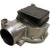
Workings of the air vane sensor
A vane type mass air flow sensor (MAF) measures the amount of air passing through the engine air intake with a metering vane placed in the air stream. This vane is held in a rest position by a spring. When air passes (engine running), the vane is rotated against the spring pressure. The more air passes, the larger the displacement of the vane becomes. The vane is connected to a slider of a potentiometer. One end of the carbon track is connected to the power supply and the other to ground. When the vane moves, the slider is pushed along the carbon track and changes the signal voltage according to the amount of passing air. This signal voltage is used by the engine control unit (ECU) to calculate the amount of air flowing into the combustion chambers.
Connecting the lab scope
Correct functioning of the air vane sensor can be checked by measuring the following signal voltages, see figure 1:
| Channel | Probe | Voltage | Range |
|---|---|---|---|
| 1 |  |
Sensor output signal | 8 V |
 |
Ground at battery | ||
| 2 |  |
Positive side of sensor power supply | 8 V |
|
Negative side of sensor power supply |
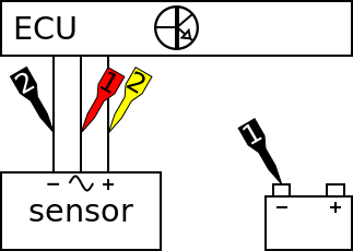
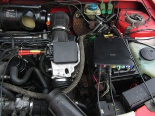
The lab scope is connected via a Measure lead TP-C1812B and Back Probe TP-BP85 to the air vane sensor. The lab scope is set to recorder mode. In recorder mode a streaming measurement is performed, continuously displaying the signals live on screen. Because the measured signals vary slowly, the Automotive Test Scope ATS5004D is set to a slow measuring speed.
Measuring
Figure 3 shows a waveform of a air vane sensor from a stationary car with running engine. The signals are measured under the following circumstances: ignition on, cranking, idle, 2000 RPM, 3000 RPM and back to idle. This signal can be downloaded and used to correctly set up the lab scope or as reference signal.
Download air vane sensor measurement
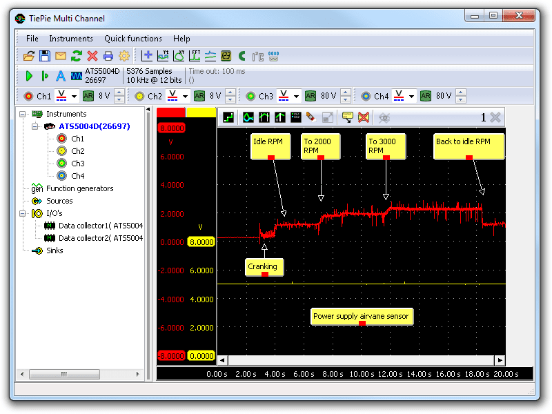
Channel 1 (red) shows the signal of the air flow meter and channel 2 (yellow) the power supply of the sensor. At the beginning of the measurement the signal shows the cranking of the engine after which the engine speed stabilizes at idle RPM. The throttle is opened twice during this measurement to increase the engine speed. The signal voltage of the air flow meter rises with the increased engine speed. Near the end of the measurement the throttle is released and the signal voltage drops until the engine is back at idling speed. The signal of the air flow meter shows spikes and a low amount of noise. This has no influence on the performance of the engine management unit because the ECU has filtered inputs.
Diagnosis
Signal values may differ on different types of engine control units and air vane sensors. Consult ATIS to get information on specific engine control units and air vane sensors.
The following signal deviations can indicate a problem:
-
No signal:
Cause: back probes have no connection (perform a connection test), no power supply, sensor defective -
Signal voltage too high:
Cause: poor or no ground on power supply, sensor defective -
Noisy signal:
Cause: wiring of signal wire or power supply damaged, poor carbon track of the potentiometer, poor connection in connector terminals -
Signal shows an offset in relation to the example signal:
Cause: poor power supply to air flow meter, false air leaks into the air intake system, sensor defective
RELATED PRODUCTS


RELATED ARTICLES
- Mass Air Flow (MAF) hot wire sensor
- With a lab scope a Mass Air Flow (MAF) sensor is measured under the following conditions: key on, cranking, idle, 2000 RPM, 3000 RPM and back to idle with an engine at operating temperature. The signal from the sensor is shown and can be downloaded. To help determining whether a MAF sensor is functioning correctly, different possible deviations from the example signal are mentioned along with probable causes.
- Manifold Absolute Pressure (MAP) sensor
- With a lab scope a Manifold Absolute Pressure (MAP) sensor is measured under the following conditions: key on, cranking, idle, 2000 RPM, 3000 RPM and back to idle with an engine at operating temperature. The signal from the sensor is shown and can be downloaded. To help determining whether a MAP sensor is functioning correctly, different possible deviations from the example signal are mentioned along with probable causes.
This document is subject to changes without notification. All rights reserved.
The information in this application note is carefully checked and is considered to be reliable, however TiePie engineering assumes no responsibility for any inaccuracies.
Safety warning:
- Before measuring, check that sources of dangerously high voltages are switched off or shielded from contact. Voltages considered to be dangerous are voltages over 30 V AC RMS, 42 V AC peak or 60 V DC.
- Keep a clean working environment when doing measurements.
- This measurement and procedures are a examples / measuring suggestions and are no prescribed protocols.
- TiePie engineering can not anticipate the safety actions that need to be taken to protect persons and appliances. Before starting a measurement, check which safety measures need to be applied.